RADIATOR INSTALLATION

-
INSTALL FAN SHROUD
-
Attach the 2 claws on the lower part of the fan shroud to the radiator assembly.
-
Attach the claw on the upper part of the fan shroud, and then install the fan shroud to the radiator assembly with the 2 bolts.
- Torque:
- 7.1 N*m { 72 kgf*cm, 63 in.*lbf }
-
-
INSTALL RADIATOR ASSEMBLY
-
Install the 2 radiator support cushions and 2 lower radiator supports to the radiator assembly.
-
Install the radiator assembly to the vehicle together with the fan shroud.
Note
Do not allow the radiator assembly to interfere with other parts.
-
-
INSTALL COOLER CONDENSER ASSEMBLY
-
Install the cooler condenser assembly to the radiator assembly with the 4 bolts.
- Torque:
- 6.0 N*m { 61 kgf*cm, 53 in.*lbf }
-
-
INSTALL HOOD LOCK CONTROL CABLE COVER (w/ Cover)
-
Attach the guide to install the hood lock control cable cover.
-
-
INSTALL UPPER RADIATOR SUPPORT
-
Install the upper radiator support with the 5 bolts.
- Torque:
- 8.0 N*m { 82 kgf*cm, 71 in.*lbf }
-
Attach the 5 wire harness clamps to connect the wire harness to the upper radiator support.
-
Connect the 3 connectors.
-
-
CONNECT HOOD LOCK CONTROL CABLE COVER (w/ Cover)
-
Attach the claw and install the 2 screws to connect the hood lock control cable cover.
-
-
CONNECT NO. 2 ENGINE ROOM WIRE
-
Attach the 6 wire harness clamps to connect the No. 2 engine room wire.
-
Connect the cooling fan ECU connector.
-
-
CONNECT NO. 2 OIL COOLER INLET HOSE
-
Connect the No. 2 oil cooler inlet hose to the radiator assembly and slide the clip to secure it.
-
Install a new No. 1 flexible hose clamp to the radiator assembly.
-
Engage the clamp to connect the No. 2 oil cooler inlet hose to the No. 1 flexible hose clamp.
-
-
CONNECT NO. 2 OIL COOLER OUTLET HOSE
-
Connect the No. 2 oil cooler outlet hose to the radiator assembly, and slide the clamp to secure the hose.
-
-
CONNECT NO. 2 RADIATOR HOSE SUB-ASSEMBLY
-
Install the No. 2 radiator hose sub-assembly to the fan shroud with the bolt.
- Torque:
- 5.0 N*m { 51 kgf*cm, 44 in.*lbf }
-
Connect the No. 2 radiator hose sub-assembly to the radiator assembly, and slide the clamp to secure the hose.
-
Install a new No. 2 radiator hose clamp to No. 2 radiator hose sub-assembly.
-
Attach the No. 2 radiator hose clamp to connect the No. 2 radiator hose sub-assembly to the fan shroud.
-
Attach the clamp to connect the reservoir tank outlet hose to the fan shroud.
-
-
INSTALL RADIATOR RESERVOIR TANK ASSEMBLY
-
Install the radiator reservoir tank assembly with the 2 bolts.
- Torque:
- 5.0 N*m { 51 kgf*cm, 44 in.*lbf }
-
Attach the clamp to connect the No. 2 engine room wire to the radiator reservoir tank assembly.
-
Connect the reservoir tank outlet hose to the radiator reservoir tank assembly, and slide the clamp to secure the hose.
-
Attach the clamp to connect the reservoir tank outlet hose to the fan shroud.
-
Install the radiator reservoir tank hose to the radiator reservoir tank assembly and radiator assembly, and slide the 2 clamps to secure the hoses.
-
Attach the clamp to connect the radiator reservoir tank hose to fan shroud.
-
-
INSTALL RADIATOR HOSE SUB-ASSEMBLY
-
Install the radiator hose sub-assembly to the water outlet sub-assembly and radiator assembly, and slide the 2 clamps to secure the hoses.
-
-
INSTALL HOOD LOCK ASSEMBLY (for LHD)
-
Connect the hood lock control cable to the hood lock.
-
Install the hood lock with the 3 bolts.
- Torque:
- 7.5 N*m { 76 kgf*cm, 66 in.*lbf }
-
-
INSTALL HOOD LOCK ASSEMBLY (for RHD)
-
Connect the hood lock control cable to the hood lock.
-
Install the hood lock with the 3 bolts.
- Torque:
- 7.5 N*m { 76 kgf*cm, 66 in.*lbf }
-
-
CONNECT HOOD LOCK CONTROL CABLE ASSEMBLY
-
Attach the clamp to connect the hood lock control cable assembly.
-
-
INSTALL HOOD LOCK RELEASE LEVER PROTECTOR
-
Install the hood lock release lever protector with the 2 clips.
-
Attach the 2 clamps and connect the connector.
-
-
INSTALL AIR CLEANER CAP WITH NO. 2 AIR CLEANER HOSE
-
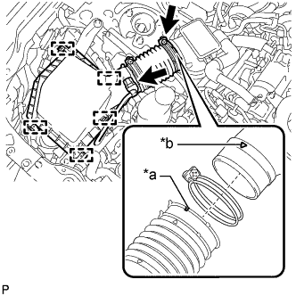
Text in Illustration *a Groove *b Matchmark Connect the air cleaner cap with No. 2 air cleaner hose to the air cleaner hose assembly.
Tech Tips
Make sure the direction of the installation is as shown in the illustration.
-
Attach the 4 clamps to install the air cleaner cap with No. 2 air cleaner hose.
-
Tighten the hose clamp.
- Torque:
- 4.0 N*m { 41 kgf*cm, 35 in.*lbf }
-
Connect the wire harness clamp to the air cleaner cap with No. 2 air cleaner hose.
-
Connect the mass air flow meter sub-assembly connector.
-
-
INSTALL NO. 1 AIR CLEANER INLET
-
Install the No. 1 air cleaner inlet with the bolt.
- Torque:
- 5.0 N*m { 51 kgf*cm, 44 in.*lbf }
-
-
ADD ENGINE COOLANT
CAUTION:
Do not remove the water filler cap sub-assembly or reservoir tank cap while the engine and radiator assembly are still hot. Pressurized hot engine coolant and steam may be released and cause serious burns.
Tech Tips
Before starting the engine to warm up the engine, turn the A/C switch off.
-
Tighten the radiator drain cock sub-assembly by hand.
-
Remove the vinyl tube from the radiator drain cock.
-
Install the No. 4 center engine under cover with the 3 screws.
-
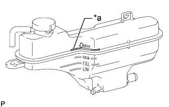
Text in Illustration *a [AR] B line Add engine coolant to the [AR] B line of the radiator reservoir tank assembly. [*1]
Standard Capacity Item Specified Condition Engine Coolant 8.4 liters (8.9 US qts, 7.4 Imp. qts) Note
-
Do not reverse the position of the reservoir tank cap and water filler cap sub-assembly when installing them. Doing so may damage the parts.
-
Do not substitute plain water for engine coolant.
-
Apply a light coat of engine coolant to the O-ring of the water filler cap sub-assembly when installing the water filler cap sub-assembly.
Tech Tips
TOYOTA vehicles are filled with TOYOTA SLLC at the factory. In order to avoid damage to the engine cooling system and other technical problems, only use TOYOTA SLLC or similar high quality ethylene glycol based non-silicate, non-amine, non-nitrite, non-borate coolant with long-life hybrid organic acid technology (coolant with long-life hybrid organic acid technology is a combination of low phosphates and organic acids).
-
-
Install the reservoir tank cap.
-
Add engine coolant to the radiator pipe filler hole.
Tech Tips
-
Install the water filler cap sub-assembly.
-
Squeeze radiator hose sub-assembly and No. 2 radiator hose sub-assembly several times by hand, and then check the level of the engine coolant.
If the engine coolant level is low, add engine coolant.
-
-
Put the engine in inspection mode (maintenance mode). [*2] Click here
-
Bleed air from the cooling system. [*3]
CAUTION:
-
Before starting the engine, turn the A/C switch off.
-
Adjust the heater control to the maximum hot setting.
-
Adjust the blower speed to the low setting.
-
Warm up the engine until the water inlet with thermostat sub-assembly opens. While the water inlet with thermostat sub-assembly is open, circulate the engine coolant for several minutes.
CAUTION:
When squeezing the radiator hose sub-assembly and No. 2 radiator hose sub-assembly :
-
Wear protective gloves.
-
Be careful as the radiator hose sub-assembly and No. 2 radiator hose sub-assembly are hot.
-
Keep your hands away from the fan and No. 2 fan.
Note
-
Make sure that the radiator reservoir tank assembly still has some engine coolant in it.
-
If the coolant temperature gauge indicates an excessive temperature, turn off the engine and let it cool.
-
If there is not enough engine coolant, the engine may overheat or be seriously damaged.
-
If the radiator reservoir tank assembly does not have enough engine coolant, perform the following: 1) stop the engine, 2) wait until the engine coolant cools down, and 3) add engine coolant until the radiator reservoir tank assembly is filled to the full line.
Tech Tips
The water inlet with thermostat sub-assembly open timing can be confirmed by squeezing the radiator hose sub-assembly by hand, and sensing vibrations when the engine coolant starts to flow inside the No. 2 radiator hose sub-assembly.
-
-
Squeeze the radiator hose sub-assembly and No. 2 radiator hose sub-assembly several times by hand to bleed air.
-
Stop the engine, and wait until the engine coolant cools down. [*4]
-
Check that the engine coolant level is between the full and low. [*5]
Tech Tips
-
If the engine coolant level is below the low, repeat steps from [*1] to [*5].
-
If the engine coolant level is above the full, drain engine coolant so that the engine coolant level is between the full and low.
-
-
-
-
INSPECT FOR COOLANT LEAK
CAUTION:
Do not remove the water filler cap sub-assembly or reservoir tank cap while the engine and radiator assembly are still hot. Pressurized hot engine coolant and steam may be released and cause serious burns.
Note
Before performing each inspection, turn the A/C switch off.
-
Remove the reservoir tank cap.
-
Fill the radiator reservoir tank assembly with coolant and attach a radiator cap tester.
-
Put the engine in inspection mode (maintenance mode). Click here
-
Warm up the engine.
-
Using a radiator cap tester, increase the pressure inside the radiator assembly to 137 kPa (1.4 kgf/cm2, 20 psi), and check that the pressure does not drop.
If the pressure drops, check the hoses, radiator assembly and engine water pump assembly for leaks. If no external leaks are found, check the heater core, cylinder block sub-assembly and cylinder head sub-assembly.
-
Remove the radiator cap tester.
-
Install the reservoir tank cap.
-
-
INSTALL ENGINE UNDER COVER
-
Install the engine under cover with the 13 screws and 3 clips.
-
-
INSTALL NO. 1 ENGINE COVER SUB-ASSEMBLY
-
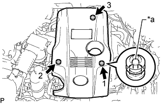
Text in Illustration *a Tip (Round Portion) Attach the 3 clips in the order shown in the illustration to install the No. 1 engine cover sub-assembly.
Note
-
Securely engage the clips.
-
If the clips are forcibly attached or struck with an object, they may be damaged.
-
-
-
INSTALL MILLIMETER WAVE RADAR SENSOR ASSEMBLY (w/ Dynamic Radar Cruise Control System)
-
ADJUST MILLIMETER WAVE RADAR SENSOR ASSEMBLY (w/ Dynamic Radar Cruise Control System)
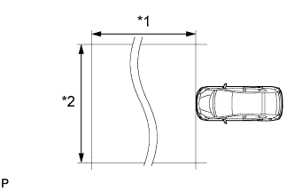
Text in Illustration *1 Approx. 10 m (32.8 ft.) *2 Approx. 14 m (45.9 ft.) Note
-
Perform measurements on a level surface.
-
Make sure that no large pieces of metal are within a 10 m (32.8 ft.) x 14 m (45.9 ft.) area in front of the vehicle. If possible, the surrounding area should also be free of large metal objects.
-
Before adjusting the radar beam axis, prepare the vehicle as follows.
-
Remove all excess weight from the vehicle (luggage, heavy objects, etc.).
-
Check the tire pressure and adjust it if necessary Click here.
-
-
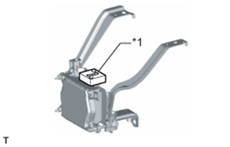
Text in Illustration *1 Level Check and adjust the vertical direction of the radar sensor.
-
Remove dust, oil and foreign matter from the radar sensor's level rack.
-
Set a level on the radar sensor's level rack.
-
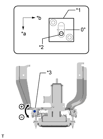
Text in Illustration *1 Level *2 Air Bubble *3 Bolt A *a FR *b LH Check that the level's air bubble is within the red frame.
OK Level's air bubble is within the red frame. If the bubble is not within the red frame, use a screwdriver to adjust bolt A until the air bubble is within the red frame.
Tech Tips
-
The adjustable range within the level's red frame is +/- 0.2°.
-
The target angle is +0.2° (upward angle of 0.2°).
Adjustment Adjustment Direction Adjustment Procedure Adjustment Angle Vertical adjustment Upward direction: Turn bolt A to negative (-) side For 1 complete turn of screwdriver, sensor moves about 0.12° Downward direction: Turn bolt A to positive (+) side
-
-
-
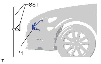
Text in Illustration *1 Millimeter Wave Radar Sensor Adjust the reflector height.
-
Adjust the reflector so that the center of SST reflector is the same height as the millimeter wave radar sensor.
- SST
- 09870-60000 ( 09870-60010 )
- 09870-60040
Tech Tips
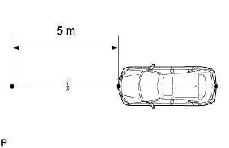
Prepare a 10 m (32.8 ft.) string, a string with a sharp-pointed weight (plumb bob), and a 5 m (16.4 ft.) tape measure.
-
-
Place the reflector.
-
Hang the string (with weight) from the center of the vehicle's rear emblem. Mark the vehicle's rear center point on the ground. Repeat for the front of the vehicle.
-
Text in Illustration *a Adjust Center By Moving String To Right And Left *b Extend String Through Front Center Mark Set one end of the 10 m (32.8 ft.) string on the vehicle's rear center point. Run the string over the vehicle's front center point to a position 5 m (16.4 ft.) beyond the vehicle's front center point as shown in the illustration. Mark the 5 m (16.4 ft.) position.
-
Place the reflector (SST) at the marked position.
Note
Perform the operation as precisely as possible.
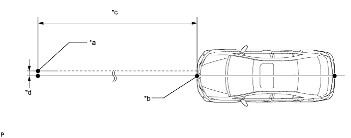
Text in Illustration *a Reflector (SST) Placement Point *b Millimeter Wave Radar Sensor Position *c 5 m (16.4 ft.) *d 13.1 mm (0.516 in.)
-
-
Check the radar beam axis.
-
When using the GTS:
-
Connect the GTS to the DLC3.
-
Turn the power switch on (IG).
-
Turn the GTS on, and turn the cruise control main switch on.
-
Select "Connect to Vehicle".
-
Select each item on the display screen and proceed to the next screen.
-
Under "System Selection Menu", select "Radar Cruise".
-
Select "Utility".
-
Select "Beam Axis Adjustment" and proceed to the next screen.
Tech Tips
A buzzer will sound for 1 second.
-
Follow the GTS display, and continue with the adjustment.
Note
-
Turn the cruise control main switch on before pressing "Next".
-
Make sure there is at least 20 cm (7.87 in.) between the radar sensor and any nearby individuals.
-
-
-
Check the following items on the radar cruise divergence data screen.
Note
While using the GTS beam axis adjustment mode, the actual direction and angle of the radar sensor may be different from the GTS data. In such a case, the deviation is displayed on the multi-information display in the combination meter.
-
Confirm that the distance value is approximately 5 m (16.4 ft.).
Tech Tips
-
A value between 0.0 m (0.0 ft.) and 6.3 m (20.7 ft.) should be indicated.
-
If the distance is 0.0 m (0.0 ft.), the sensor cannot detect the target. Reconfirm that there is no metal in the specified area in front of the vehicle (refer to the Notice at the beginning of this adjustment procedure).
-
-
Confirm that the left/right side value is between 0.0 m (0.0 ft.) and 6.3 m (20.7 ft.).
Tech Tips
If the distance is 0.0 m (0.0 ft.), the sensor cannot detect the target. Reconfirm that there is no metal in the specified area in front of the vehicle (refer to the Notice at the beginning of this adjustment procedure).
-
-
-
Check and adjust the horizontal direction of the radar sensor.
-
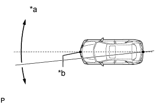
Check that the divergence of the radar beam axis is 0°.
Standard 0° (Both right and left) If the axis is not as specified, use a screwdriver to adjust bolt B until the divergence of the radar beam axis is 0°.
-
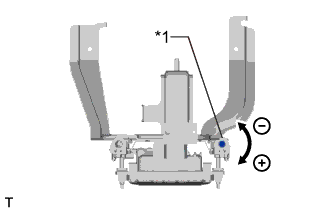
Text in Illustration *1 Bolt B Based on the measured divergence of the beam axis, turn and adjust bolt B for horizontal adjustment of the millimeter wave radar sensor using a screwdriver.
Adjustment Adjustment Direction Adjustment Procedure Adjustment Angle Horizontal adjustment Right direction: Turn bolt B to positive (+) side. For 1 complete turn of screwdriver, sensor moves about 0.07° Left direction: Turn bolt B to negative (-) side. Tech Tips
If the value does not change to 0°, it is possible that the sensor is aiming at something different. Reconfirm that there are no reflective materials in the surrounding area.
-
Finish the beam axis adjustment.
-
Disconnect the GTS from the DLC3.
-
-
Recheck and readjust the vertical direction of the radar sensor.
-
Text in Illustration *1 Level Set a level on the radar sensor's level rack.
-
Text in Illustration *1 Level *2 Air Bubble *3 Bolt A *a FR *b LH Check that the level's air bubble is within the red frame.
OK Level's air bubble is within the red frame. If the bubble is not within the red frame, use a screwdriver to adjust bolt A until the level's air bubble is within the red frame.
Tech Tips
-
The adjustable range within the red frame is +/- 0.2°.
-
The target angle is + 0.2° (upward angle of 0.2°).
Adjustment Adjustment Direction Adjustment Procedure Adjustment Angle Vertical adjustment Upward direction: Turn bolt A to negative (-) side For 1 complete turn of screwdriver, sensor moves about 0.12° Downward direction: Turn bolt A to positive (+) side
-
-
-
-
INSTALL FRONT BUMPER COVER
-
for Sport Package Click here
-
except Sport Package Click here
-