FUEL PUMP (for High Pressure) INSTALLATION

Tech Tips
Perform "Inspection After Repairs" after replacing the fuel pump assembly Click here.
-
SET FUEL PUMP ASSEMBLY
-
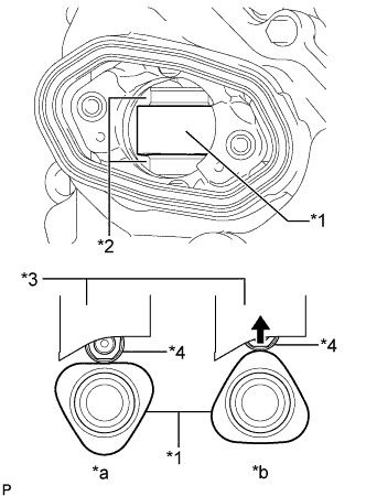
Text in Illustration *1 Camshaft *2 Oil Collection Area *3 Fuel Pump lifter guide *4 Fuel Pump lifter assembly *a OK *b NG Turn the crankshaft so that the flat surface of the camshaft is facing upward from the fuel pump assembly hole of the cylinder head cover.
Tech Tips
By performing the above procedure, the protruding part of the camshaft does not push up the drive face of the pump when installing the fuel pump assembly, thus making installation of the fuel pump and No. 2 fuel pipe sub-assembly easier.
-
Fill the cylinder head oil collection areas with 30 cc (1.8 cu.in.) of engine oil from the fuel pump assembly hole of the cylinder head cover.
-
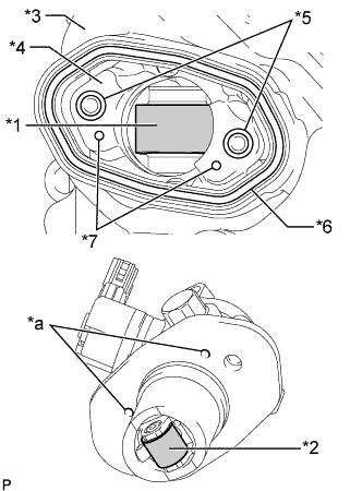
Text in Illustration *1 Pump Drive Cam (Engine Oil Application Point) *2 Pump Lifter (Engine Oil Application Point) *3 Cylinder head cover *4 Pump Housing *5 O-ring *6 Fuel Pump Spacer Gasket *7 Knock Pin *a Positioning Knock Hole Apply engine oil to the pump drive cam and pump lifter.
-
Install 2 new O-rings to the pump housing.
-
Install a new fuel pump spacer gasket to the head cover.
-
Install a new O-ring to the fuel pump.
-
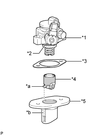
Text in Illustration *1 Fuel Pump *2 O-ring *3 Fuel Pump Insulator *4 Fuel Pump Lifter Assembly *5 Fuel Pump Lifter Guide *a Stopper Key *b Key Groove 
Engine Oil Application Point Apply engine oil to the inside of the fuel pump lifter guide and the outside of the fuel pump lifter assembly.
-
Set the cylinder head cover on the fuel pump assembly as shown in the illustration.
Note
-
Align the stopper key of the fuel pump lifter assembly with the key groove of the fuel pump lifter guide.
-
Align the positioning knock pin of the pump housing with the positioning knock hole of the fuel pump lifter guide.
-
Make sure not to hit the pump lifter part of the fuel pump filter assembly when installing.
-
-
Temporarily install the fuel pump assembly with the 2 bolts, leaving some allowance for left and right movement.
-
-
TEMPORARILY INSTALL NO. 1 FUEL PIPE SUB-ASSEMBLY
-
Temporarily install the union nuts on the fuel delivery pipe side of the No. 1 fuel pipe sub-assembly until they are completely tightened.
-
Temporarily install the union nuts on the fuel pump assembly side of the No. 1 fuel pipe sub-assembly until they are completely tightened.
Note
Do not damage the seals of the union nuts of the No. 1 fuel pipe sub-assembly when installing.
-
-
INSTALL FUEL PUMP ASSEMBLY
Tech Tips
Perform "Inspection After Repairs" after replacing the fuel pump assembly Click here.
-
Uniformly tighten the 2 bolts in several steps to secure the fuel pump assembly to the cylinder head cover.
- Torque:
- 30 N*m { 306 kgf*cm, 22 ft.*lbf }
-
Connect the connector to the fuel pump assembly.
-
-
INSTALL NO. 1 FUEL PIPE SUB-ASSEMBLY
-
Using a 17 mm union nut wrench, tighten the union nuts on the fuel delivery pipe side of the No. 1 fuel pipe sub-assembly.
- Torque:
- 35 N*m { 357 kgf*cm, 26 ft.*lbf }
Note
-
When a torque wrench is combined with a union nut wrench and used to tighten parts, if the reading from the torque wrench reaches the torque specification, the actual torque will be excessive due to the increase in the total length of the wrench Click here.
-
Do not adjust the torque in the loosening direction.
-
The No. 1 fuel pipe sub-assembly can be reused 10 times.
Tech Tips
-
This torque value is effective when the union nut wrench is parallel to the torque wrench.
-
Install the union nut wrench parallel with the torque wrench.
-
Using a 17 mm union nut wrench, tighten the union nuts on the fuel pump assembly side of the No. 1 fuel pipe sub-assembly.
- Torque:
- 35 N*m { 357 kgf*cm, 26 ft.*lbf }
Note
-
When a torque wrench is combined with a union nut wrench and used to tighten parts, if the reading from the torque wrench reaches the torque specification, the actual torque will be excessive due to the increase in the total length of the wrench Click here.
-
Do not adjust the torque in the loosening direction.
-
The No. 1 fuel pipe sub-assembly can be reused 10 times.
Tech Tips
-
This torque value is effective when the union nut wrench is parallel to the torque wrench.
-
Install the union nut wrench parallel with the torque wrench.
-
-
INSTALL NO. 1 FUEL PIPE
-
Apply engine oil to the threads of the union bolt.
-
Install the No. 1 fuel pipe and 2 new gaskets with the union bolt.
- Torque:
- 35 N*m { 357 kgf*cm, 26 ft.*lbf }
-
Connect the No. 2 fuel tube sub-assembly to the No. 1 fuel pipe Click here.
-
-
INSTALL NO. 3 WATER BY-PASS PIPE
-
Connect the 2 water by-pass hoses and install the No. 3 water by-pass pipe.
-
Install the bolt.
- Torque:
- 10 N*m { 102 kgf*cm, 7 ft.*lbf }
-
Attach the 2 wire harness clamps to the No. 3 water by-pass pipe.
-
Connect the 2 heater water hoses.
-
Install the 2 water hose sets.
-
-
INSTALL INTAKE MANIFOLD