FRONT WHEEL ALIGNMENT ADJUSTMENT

Note
If the wheel alignment has been adjusted, or if suspension or underbody components have been removed/installed or replaced, be sure to perform the following initialization procedure in order for the system to function normally.
-
Disconnect the cable from the negative battery terminal for more than 2 seconds.
-
Reconnect the cable to the negative battery terminal.
-
Perform zero point calibration of the yaw rate and acceleration sensor and test mode inspection.
-
INSPECT TIRES
Tech Tips
Inspect the tires Click here.
-
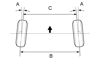
MEASURE VEHICLE HEIGHT
-
Bounce the vehicle at the corners up and down to stabilize the suspension and inspect vehicle height.
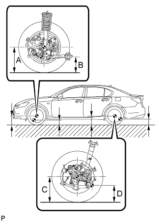
Vehicle height (Unloaded vehicle) Front (A-B) Rear (C-D) 114 mm
(4.49 in.)
97 mm
(3.82 in.)
Measuring points A Ground clearance of front wheel center B Ground clearance of front center position of front suspension lower arm assembly front bush installation C Ground clearance of rear wheel center D Ground clearance of rear center position of rear suspension No. 2 arm bush installation bolt screw thread Note
-
The standard value shown here is a value that is used for adjusting the wheel alignment and does not indicate the height of an actual vehicle.
-
Before inspecting the wheel alignment, adjust the vehicle height to the specified value.
Tech Tips
Bounce the vehicle at the corners up and down to stabilize the suspension and inspect the vehicle height.
-
-
-
INSPECT CAMBER, CASTER AND STEERING AXIS INCLINATION
-
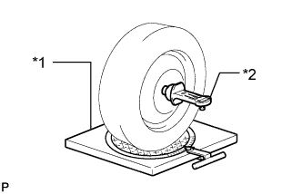
Text in Illustration *1 Wheel Alignment Tester *2 Gauge Put the front wheel on the center of the alignment tester.
-
Remove the center ornament.
-
Install the camber-caster-steering axis inclination gauge at the center of the axle hub or drive shaft.
-
Inspect the camber, caster and steering axis inclination.
Camber, caster and steering axis inclination (Unloaded vehicle) Camber -0°14' +/-45'
(-0.23° +/-0.75°)
Right-left Error
45' (0.75°) or less
Caster 7°55' +/-45'
(7.92° +/-0.75°)
Right-left Error
45' (0.75°) or less
Steering axis inclination 10°28' +/-45'
(10.47° +/-0.75°)
Right-left Error
45' (0.75°) or less
Note
-
Inspect while the vehicle is empty.
-
The maximum tolerance of right and left difference for the camber and caster is 45' (0.75°) or less.
-
-
Remove the camber-caster-steering axis inclination gauge and attachment.
-
Install the center ornament.
If the caster and steering axis inclination are not within the specified values, after the camber has been correctly adjusted, recheck the suspension parts for damaged and/or worn out parts.
-
-
INSPECT FRONT SUSPENSION
-
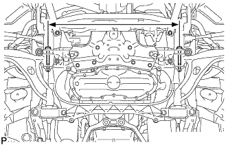
Inspect the front suspension member.
-
Measure the dimension between the center of the installation bolts of the front suspension lower arm.
Standard 692.5 to 699.5 mm (2.28 to 2.29 ft.) If the result is not within the specification, replace the front suspension member.
-
-
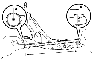
Inspect the front suspension lower arm assembly.
-
Remove the front suspension lower arm assembly, see the REPLACEMENT Click here.
-
Measure the dimension between the center of the front suspension lower arm assembly bush and position A.
Standard 396 mm (1.30 ft.) Tech Tips
If the dimension of the front suspension lower arm assembly changes 2 mm (0.079 in.), the camber will change approximately 15' (0.25°).
-
-
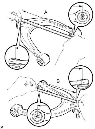
Inspect the front suspension upper arm assembly.
-
Remove the front suspension upper arm assembly, see the REPLACEMENT Click here.
-
Measure the dimension between the center of the front suspension upper arm assembly bush and the ball joint stud.
Standard A 250 mm (9.84 in.) B 231 mm (9.09 in.) Tech Tips
If the dimension of the front suspension upper arm assembly changes 2 mm (0.079 in.), the camber will change approximately 15' (0.25°).
-
-
-
ADJUST CASTER
-
Based on the caster inspection values, select a lower No. 2 arm bracket.
Part No. Information Part No. Offset (position) Part Name 48075-30060 0' Lower Arm Bush Bracket Sub-assembly RH 48075-30080 +20' Lower Arm Bush Bracket Sub-assembly RH 48075-30090 -20' Lower Arm Bush Bracket Sub-assembly RH 48076-30060 0' Lower Arm Bush Bracket Sub-assembly LH 48076-30080 +20' Lower Arm Bush Bracket Sub-assembly LH 48076-30090 -20' Lower Arm Bush Bracket Sub-assembly LH
-
-
INSPECT TOE-IN
-
Bounce the vehicle at the corners up and down to stabilize the suspension and inspect toe-in.
Text in Illustration 
Front of Vehicle Toe-in (Unloaded Vehicle) Toe-in A: 0°2.6' +/-5' (0.04° +/-0.09°)
B - C: 1 +/-2 mm (0.04 +/-0.08 in.)
Tech Tips
If toe-in is not within the specified range, adjust it at the rack ends.
-
-
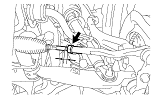
ADJUST TOE-IN
-
Measure the thread lengths of the right and left rack ends.
Standard Difference in thread length of 1.5 mm (0.059 in.) or less -
Remove the rack boot set clips.
-
Loosen the tie rod end lock nuts.
-
Adjust the rack ends if the difference in thread length between the right and left rack ends is not within the specified range.
-
Extend the shorter rack end if the measured toe-in deviates toward the inner-side.
-
Shorten the longer rack end if the measured toe-in deviates toward the outer-side.
-
-
Turn the right and left rack ends by an equal amount to adjust toe-in.
Tech Tips
Try to adjust toe-in to the center of the specified range.
-
Make sure that the lengths of the right and left rack ends are the same.
-
Tighten the tie rod end lock nuts.
- Torque:
- 56 N*m { 571 kgf*cm, 41 ft.*lbf }
Note
Temporarily tighten the lock nut while holding the hexagonal part of the steering rack end so that the lock nut and the steering rack end do not turn together. Hold the width across flat of the tie rod end and tighten the lock nut.
-
Place the boots on the seats and install the clips.
Note
Perform VGRS calibration after adjusting toe-in.
Tech Tips
Make sure that the boots are not twisted.
-
-
INSPECT WHEEL ANGLE
-
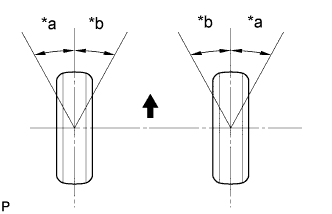
Text in Illustration *a Inside *b Outside Front of the vehicle Turn the steering wheel fully left and right and measure the turning angle.
Wheel turning angle Outside wheel Inside wheel 36°01' +/-2°
(36.02° +/-2°)
41°35'
(41.58°)
If the right and left inside wheel angles differ from the specified range, check the right and left rack end lengths.
-
-
PLACE FRONT WHEELS FACING STRAIGHT AHEAD
-
REMOVE LUGGAGE COMPARTMENT FLOOR MAT
-
Remove the luggage compartment floor mat.
-
-
REMOVE LUGGAGE COMPARTMENT TRIM COVER LH
-
Remove the luggage compartment trim cover.
-
-
DISCONNECT CABLE FROM AUXILIARY BATTERY NEGATIVE TERMINAL
Note
Disconnect the cable from the negative battery terminal for more than 2 seconds.
-
CONNECT CABLE TO AUXILIARY BATTERY NEGATIVE TERMINAL
Note
When disconnecting the cable, some systems need to be initialized after the cable is reconnected Click here.
-
INSTALL LUGGAGE COMPARTMENT TRIM COVER LH
-
Install the luggage compartment trim cover.
-
-
INSTALL LUGGAGE COMPARTMENT FLOOR MAT
-
Install the luggage compartment floor mat.
-
-
PERFORM YAW RATE SENSOR ZERO POINT CALIBRATION
-
CHECK STEERING ANGLE SENSOR ZERO POINT CALIBRATION
-
PERFORM VARIABLE GEAR RATIO STEERING SYSTEM CALIBRATION (w/ VGRS)