СИСТЕМА АВТОМАТИЧЕСКОЙ ТРАНСМИССИИ, Diagnostic DTC:P0705
| DTC Code | DTC Name |
|---|---|
| P0705 | Transmission Range Sensor Circuit Malfunction (PRNDL Input) |
DESCRIPTION
The park/neutral position switch detects the shift lever position and sends signals to the TCM.
| DTC No. | DTC Detection Condition | Trouble Area |
|---|---|---|
| P0705 | When condition (A) or (B) is met: (A) Any 2 or more of the following conditions are met simultaneously (2-trip detection logic)
(B) All signals are off simultaneously for P, N, R and D switches (2 trip detection logic) |
|
MONITOR DESCRIPTION
This DTC indicates a problem with the park/neutral position switch assembly or the wire harness in the park/neutral position switch assembly circuit.
The park/neutral position switch assembly detects the shift lever position and sends signals to the TCM.
For safety, the park/neutral position switch assembly detects the shift lever position so that the engine can be started only when the shift lever is in P or N.
The park/neutral position switch assembly sends a signal to the TCM according to the shift lever position (P, N, R or D).
The TCM determines that there is a problem with the switch or related parts if it receives more than 1 position signal simultaneously. The TCM will illuminate the MIL and store the DTC.
WIRING DIAGRAM
Refer to DTC P0617 Click here.
INSPECTION PROCEDURE
Note
Perform registration and/or initialization when parts related to the automatic transmission are replaced Click here.
PROCEDURE
-
READ VALUE USING GTS (SHIFT SW STATUS)
-
Connect the GTS to the DLC3.
-
Turn the engine switch on (IG).
-
Turn the GTS on.
-
Enter the following menus: Powertrain / ECT / Data List / Shift SW Status (P Range), Shift SW Status (R Range), Shift SW Status (N Range), Shift SW Status (D Range).
-
According to the display on the GTS, read the Data List.
ECT Tester Display Measurement Item/Range Normal Condition Diagnostic Note Shift SW Status (P Range) Park/neutral position switch status/
ON or OFF
-
ON: Shift lever is in P
-
OFF: Shift lever is not in P
When shift lever position displayed on the GTS differs from actual position, adjustment of park/neutral position switch assembly or shift cable may be incorrect. Shift SW Status (R Range) Park/neutral position switch status/
ON or OFF
-
ON: Shift lever is in R
-
OFF: Shift lever is not in R
When shift lever position displayed on the GTS differs from actual position, adjustment of park/neutral position switch assembly or shift cable may be incorrect. Shift SW Status (N Range) Park/neutral position switch status/
ON or OFF
-
ON: Shift lever is in N
-
OFF: Shift lever is not in N
When shift lever position displayed on the GTS differs from actual position, adjustment of park/neutral position switch assembly or shift cable may be incorrect. Shift SW Status (D Range) Park/neutral position switch status/
ON or OFF
-
ON: Shift lever is in D or M
-
OFF: Shift lever is not in D or M
When shift lever position displayed on the GTS differs from actual position, adjustment of park/neutral position switch assembly or shift cable may be incorrect. Result Result Proceed to Data List value is not within the normal condition A Data List value is within the normal condition B -
B 
REPLACE TCM Click here
A 
-
-
INSPECT PARK/NEUTRAL POSITION SWITCH ASSEMBLY
-
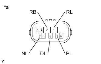
Text in Illustration *a Component without harness connected
(Park/Neutral Position Switch Assembly)
Disconnect the park/neutral position switch assembly connector.
-
Measure the resistance according to the value(s) in the table below.
Standard Resistance Tester Connection Condition Specified Condition 6 (PL) - 2 (RB) Shift lever in P Below 1 Ω 1 (RL) - 2 (RB) Shift lever in R Below 1 Ω 9 (NL) - 2 (RB) Shift lever in N Below 1 Ω 7 (DL) - 2 (RB) Shift lever in D, M, "+" or "-" Below 1 Ω 6 (PL) - 2 (RB) Shift lever not in P 10 kΩ or higher 1 (RL) - 2 (RB) Shift lever not in R 10 kΩ or higher 9 (NL) - 2 (RB) Shift lever not in N 10 kΩ or higher 7 (DL) - 2 (RB) Shift lever not in D, M, "+" or "-" 10 kΩ or higher
NG 
REPLACE PARK/NEUTRAL POSITION SWITCH ASSEMBLY Click here
OK
-
-
CHECK PARK/NEUTRAL POSITION SWITCH ASSEMBLY (POWER SOURCE)
-
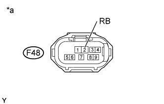
Text in Illustration *a Front view of wire harness connector
(to Park/Neutral Position Switch Assembly)
Disconnect the park/neutral position switch assembly connector.
-
Turn the engine switch on (IG).
-
Measure the voltage according to the value(s) in the table below.
Standard Voltage Tester Connection Switch Condition Specified Condition F48-2 (RB) - Body ground Engine switch on (IG) 11 to 14 V
NG
REPAIR OR REPLACE HARNESS OR CONNECTOR (PARK/NEUTRAL POSITION SWITCH ASSEMBLY - BATTERY)
OK
-
-
CHECK HARNESS AND CONNECTOR (PARK/NEUTRAL POSITION SWITCH ASSEMBLY - TCM)
-
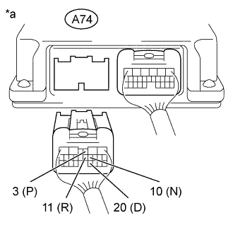
Text in Illustration *a Rear view of wire harness connector
(to TCM)
Disconnect the TCM connector.
-
Turn the engine switch on (IG).
-
Measure the voltage according to the value(s) in the table below.
Standard Voltage Tester Connection Condition Specified Condition A74-3 (P) - Body ground
-
Engine switch on (IG)
-
Shift lever in P
11 to 14 V A74-11 (R) - Body ground
-
Engine switch on (IG)
-
Shift lever in R
11 to 14 V* A74-10 (N) - Body ground
-
Engine switch on (IG)
-
Shift lever in N
11 to 14 V A74-20 (D) - Body ground
-
Engine switch on (IG)
-
Shift lever in D, M, "+" or "-"
11 to 14 V A74-3 (P) - Body ground
-
Engine switch on (IG)
-
Shift lever not in P
Below 1 V A74-11 (R) - Body ground
-
Engine switch on (IG)
-
Shift lever not in R
Below 1 V A74-10 (N) - Body ground
-
Engine switch on (IG)
-
Shift lever not in N
Below 1 V A74-20 (D) - Body ground
-
Engine switch on (IG)
-
Shift lever not in D, M, "+" or "-"
Below 1 V Tech Tips
*: The voltage will drop slightly due to the turning on of the back-up light.
-
NG
REPAIR OR REPLACE HARNESS OR CONNECTOR
OK
-
-
REPLACE TCM
-
Replace the TCM Click here.
NEXT 
PERFORM A/T CODE REGISTRATION Click here
-