CAN COMMUNICATION SYSTEM (for LHD), Diagnostic DTC:U1119

| DTC Code | DTC Name |
|---|---|
| U1119 | Lost Communication with Object Recognition ECU (CAN) |
DESCRIPTION
Tech Tips
Because of the location of the lane recognition camera assembly, it is subject to high temperatures. If the lane recognition camera sensor assembly becomes too hot, the power source is shut down to protect the system. At that time CAN communication also stops. However, in order to inform the driving support ECU that CAN communication has not stopped because of a CAN communication error, on/off signals are periodically sent from the HITP terminal.
| DTC Code | DTC Detection Condition | Trouble Area |
|---|---|---|
| U1119 | There is no communication from the lane recognition camera sensor assembly. |
|
-
For vehicles with a lane-keeping assist system.
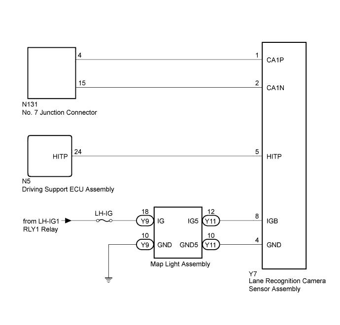
WIRING DIAGRAM
INSPECTION PROCEDURE
Note
-
Because the order of diagnosis is important to allow correct diagnosis, make sure to begin troubleshooting using How to Proceed with Troubleshooting when CAN communication system related DTCs are output Click here.
-
Before measuring the resistance of the CAN bus, turn the engine switch off and leave the vehicle for 1 minute or more without operating the key, switches or opening or closing the doors. After that, disconnect the cable from the negative (-) battery terminal and leave the vehicle for 1 minute or more before measuring the resistance.
-
After turning the engine switch off, waiting time may be required before disconnecting the cable from the battery terminal. Therefore, make sure to read the disconnecting the cable from the battery terminal notice before proceeding with work Click here.
-
Inspect the fuses for circuits related to this system before performing the following inspection procedure.
-
After performing repairs, perform the DTC check procedure and confirm that the DTCs are not output again.
-
DTC check procedure: Allow the lane-keeping assist system to operate for 0.65 seconds or more.
-
After the repair, perform CAN Bus Check and check that all the ECUs and sensors connected to the CAN communication system are displayed Click here.
Tech Tips
-
Operating the engine switch, any switches or any doors triggers related ECU and sensor communication with the CAN, which causes resistance variation.
-
Even after DTCs are cleared, if a DTC is stored again after driving the vehicle for a while, the malfunction may be occurring due to vibration of the vehicle. In such a case, wiggling the ECUs or wire harness while performing the inspection below may help determine the cause of the malfunction.
PROCEDURE
-
RECONFIRM DTC OUTPUT
-
Reconfirm DTCs.
Tech Tips
If DTC U1002 is output from Gateway of the driving support ECU assembly, this indicates a sub bus 13 malfunction. Troubleshoot for DTC U1002 and check for malfunctions in sub bus 13.
Result Result Proceed to DTC U1002 is not output from driving support ECU assembly. A DTC U1002 is output from driving support ECU assembly. B
B 
GO TO DIAGNOSIS PROCEDURE INDICATED BY OUTPUT DTC Click here
A 
-
-
READ VALUE USING GTS (RECOG ECU H TEMP HIST)
-
Use the Data List to check if the lane recognition camera sensor assembly is functioning properly Click here.
Pre-Crash 2 Tester Display Measurement Item/Range Normal Condition Diagnostic Note Recog ECU H Temp Hist Lane recognition camera sensor temperature condition history / ON or OFF OFF: No history of excessive temperature
ON: History of excessive temperature
- Result Result Proceed to History of excessive temperature A No history of excessive temperature B
B 
CHECK FOR OPEN IN CAN BUS WIRE (LANE RECOGNITION CAMERA SENSOR ASSEMBLY CAN BRANCH WIRE) Click here
A
-
-
CHECK HARNESS AND CONNECTOR (LANE RECOGNITION CAMERA SENSOR ASSEMBLY - DRIVING SUPPORT ECU ASSEMBLY)
-
Disconnect the Y7 lane recognition camera sensor assembly connector.
-
Disconnect the N5 driving support ECU assembly connector.
-
Measure the resistance according to the value(s) in the table below.
Standard Resistance Tester Connection Condition Specified Condition Y7-5 (HITP) - N5-24 (HITP) Always Below 1 Ω Y7-5 (HITP) - Body ground Always 10 kΩ or higher
NG
REPAIR OR REPLACE HARNESS OR CONNECTOR
OK
-
-
CHECK FOR OPEN IN CAN BUS WIRE (LANE RECOGNITION CAMERA SENSOR ASSEMBLY CAN BRANCH WIRE)
-
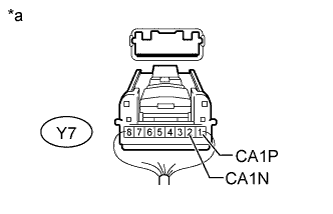
Text in Illustration *a Rear view of wire harness connector
(to Lane Recognition Camera Sensor Assembly)
Disconnect the cable from the negative (-) battery terminal.
-
Disconnect the lane recognition camera sensor assembly connector.
-
Measure the resistance according to the value(s) in the table below.
Standard Resistance Tester Connection Condition Specified Condition Y7-1 (CA1P) - Y7-2 (CA1N) Cable disconnected from negative (-) battery terminal 54 to 69 Ω
NG
REPAIR OR REPLACE LANE RECOGNITION CAMERA SENSOR ASSEMBLY CAN BRANCH WIRE OR CONNECTOR (CA1P, CA1N)
OK
-
-
CHECK HARNESS AND CONNECTOR (LANE RECOGNITION CAMERA SENSOR ASSEMBLY - BATTERY AND BODY GROUND)
-
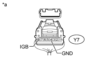
Text in Illustration *a Rear view of wire harness connector
(to Lane Recognition Camera Sensor Assembly)
Connect the cable to the negative (-) battery terminal.
Note
When connecting the cable, some systems need to be initialized after the cable is reconnected Click here.
-
Measure the voltage according to the value(s) in the table below.
Standard Voltage Tester Connection Switch Condition Specified Condition Y7-8 (IGB) - Body ground Engine switch on (IG) 11 to 14 V -
Measure the resistance according to the value(s) in the table below.
Standard Resistance Tester Connection Condition Specified Condition Y7-4 (GND) - Body ground Always Below 1 Ω
NG
REPAIR OR REPLACE HARNESS OR CONNECTOR (MAP LIGHT ASSEMBLY CIRCUIT)
OK 
REPLACE LANE RECOGNITION CAMERA SENSOR ASSEMBLY Click here
-