AUDIO AND VISUAL SYSTEM, Diagnostic DTC:B15C3

| DTC Code | DTC Name |
|---|---|
| B15C3 | Speaker Output Short |
DESCRIPTION
| DTC Code | DTC Detection Condition | Trouble Area |
|---|---|---|
| B15C3 | A short is detected in the speaker output circuit. |
|
-
*: w/ Emergency Call Switch
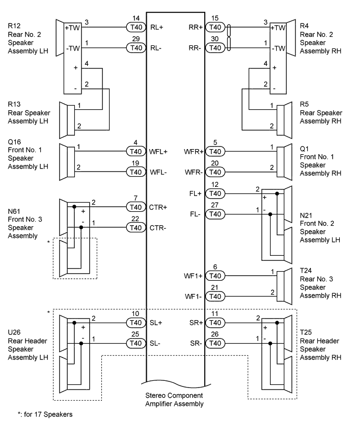
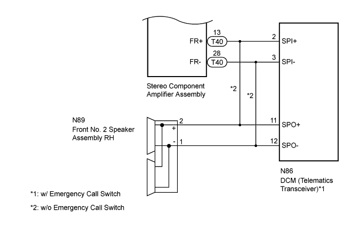
WIRING DIAGRAM
INSPECTION PROCEDURE
Tech Tips
After the inspection is completed, clear the DTCs.
PROCEDURE
-
CHECK DTC
-
Clear the DTC Click here.
NEXT 
-
-
CHECK DTC
-
Recheck for DTCs and check if the same DTC is output again Click here.
OK No DTC is output.
NG 
CHECK HARNESS AND CONNECTOR (STEREO COMPONENT AMPLIFIER ASSEMBLY - SPEAKERS AND DCM [TELEMATICS TRANSCEIVER]) Click here
OK 
USE SIMULATION METHOD TO CHECK Click here
-
-
CHECK HARNESS AND CONNECTOR (STEREO COMPONENT AMPLIFIER ASSEMBLY - SPEAKERS AND DCM [TELEMATICS TRANSCEIVER])
-
*1: for RH Side
-
*2: for LH Side
-
*3: for 17 Speakers
-
*4: w/ Emergency Call Switch
-
*5: w/o Emergency Call Switch
-
Disconnect the T40 stereo component amplifier assembly connector.
-
Disconnect the Q1*1 and/or Q16*2 front No. 1 speaker assembly connector.
-
Disconnect the N89*1 and/or N21*2 front No. 2 speaker assembly connector.
-
Disconnect the N61 front No. 3 speaker assembly connector.
-
Disconnect the R4*1 and/or R12*2 rear No. 2 speaker assembly connector.
-
Disconnect the T24 rear No. 3 speaker assembly connector.
-
Disconnect the T25*1 and/or U26*2 rear header speaker assembly*3 connector.
-
Disconnect the N86*4 DCM (telematics transceiver) connector.
-
Measure the resistance according to the value(s) in the table below.
Standard Resistance Tester Connection Condition Specified Condition T40-5 (WFR+) - Q1-1 (WF+) Always Below 1 Ω T40-20 (WFR-) - Q1-2 (WF-) Always Below 1 Ω T40-4 (WFL+) - Q16-1 (WF+) Always Below 1 Ω T40-19 (WFL-) - Q16-2 (WF-) Always Below 1 Ω T40-13 (FR+) - N86-2 (SPI+)*4 Always Below 1 Ω T40-28 (FR-) - N86-3 (SPI-)*4 Always Below 1 Ω T40-13 (FR+) - N89-2 (+)*5 Always Below 1 Ω T40-28 (FR-) - N89-1 (-)*5 Always Below 1 Ω T40-12 (FL+) - N21-2 (+) Always Below 1 Ω T40-27 (FL-) - N21-1 (-) Always Below 1 Ω T40-7 (CTR+) - N61-2 (+) Always Below 1 Ω T40-22 (CTR-) - N61-1 (-) Always Below 1 Ω T40-15 (RR+) - R4-3 (+TW) Always Below 1 Ω T40-30 (RR-) - R4-1 (-TW) Always Below 1 Ω T40-14 (RL+) - R12-3 (+TW) Always Below 1 Ω T40-29 (RL-) - R12-1 (-TW) Always Below 1 Ω T40-6 (WF1+) - T24-1 Always Below 1 Ω T40-21 (WF1-) - T24-2 Always Below 1 Ω T40-11 (SR+) - T25-2 (+)*3 Always Below 1 Ω T40-26 (SR-) - T25-1 (-)*3 Always Below 1 Ω T40-10 (SL+) - U26-2 (+)*3 Always Below 1 Ω T40-25 (SL-) - U26-1 (-)*3 Always Below 1 Ω T40-5 (WFR+) - Body ground Always 10 kΩ or higher T40-20 (WFR-) - Body ground Always 10 kΩ or higher T40-4 (WFL+) - Body ground Always 10 kΩ or higher T40-19 (WFL-) - Body ground Always 10 kΩ or higher T40-13 (FR+) - Body ground Always 10 kΩ or higher T40-28 (FR-) - Body ground Always 10 kΩ or higher T40-12 (FL+) - Body ground Always 10 kΩ or higher T40-27 (FL-) - Body ground Always 10 kΩ or higher T40-7 (CTR+) - Body ground Always 10 kΩ or higher T40-22 (CTR-) - Body ground Always 10 kΩ or higher T40-15 (RR+) - Body ground Always 10 kΩ or higher T40-30 (RR-) - Body ground Always 10 kΩ or higher T40-14 (RL+) - Body ground Always 10 kΩ or higher T40-29 (RL-) - Body ground Always 10 kΩ or higher T40-6 (WF1+) - Body ground Always 10 kΩ or higher T40-21 (WF1-) - Body ground Always 10 kΩ or higher T40-11 (SR+) - Body ground Always 10 kΩ or higher T40-26 (SR-) - Body ground Always 10 kΩ or higher T40-10 (SL+) - Body ground Always 10 kΩ or higher T40-25 (SL-) - Body ground Always 10 kΩ or higher
NG 
REPAIR OR REPLACE HARNESS OR CONNECTOR
OK
-
-
INSPECT FRONT NO. 1 SPEAKER ASSEMBLY
-
Disconnect the front No. 1 speaker assembly connector.
-
Measure the resistance according to the value(s) in the table below.
Standard Resistance for 17 Speakers Tester Connection Condition Specified Condition 1 - 2 Always 4.2 to 6.2 Ω for 12 Speakers Tester Connection Condition Specified Condition 1 - 2 Always 4.0 Ω
NG
REPLACE FRONT NO. 1 SPEAKER ASSEMBLY Click here
OK
-
-
CHECK FRONT NO. 2 SPEAKER ASSEMBLY
-
Temporarily replace the front No. 2 speaker assembly with a new or normally functioning one Click here.
-
Check for DTCs and check if the same DTCs is output Click here.
OK No DTCs are output. Result Result Proceed to OK A NG (w/ Emergency Call Switch) B NG (except Emergency Call Switch and 17 Speakers) C NG (except Emergency Call Switch and 12 Speakers) D
B
CHECK HARNESS AND CONNECTOR (DCM [TELEMATICS TRANSCEIVER] - FRONT NO. 2 SPEAKER RH) Click here
C
CHECK FRONT NO. 3 SPEAKER ASSEMBLY Click here
D
INSPECT FRONT NO. 3 SPEAKER ASSEMBLY Click here
A
END (FRONT NO. 2 SPEAKER ASSEMBLY IS DEFECTIVE)
-
-
CHECK HARNESS AND CONNECTOR (DCM [TELEMATICS TRANSCEIVER] - FRONT NO. 2 SPEAKER RH)
-
Disconnect the N86 DCM (telematics transceiver) connector.
-
Disconnect the N89 front No. 2 speaker assembly RH connector.
-
Measure the resistance according to the value(s) in the table below.
Standard Resistance Tester Connection Condition Specified Condition N86-11 (SPO+) - N89-2 (+) Always Below 1 Ω N86-12 (SPO-) - N89-1 (-) Always Below 1 Ω N86-11 (SPO+) - Body ground Always 10 kΩ or higher N86-12 (SPO-) - Body ground Always 10 kΩ or higher
NG
REPAIR OR REPLACE HARNESS OR CONNECTOR
OK
-
-
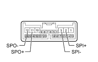
INSPECT DCM (TELEMATICS TRANSCEIVER)
-
Remove the DCM (telematics transceiver) Click here.
-
Measure the resistance according to the value(s) in the table below.
Standard Resistance Tester Connection Condition Specified Condition 2 (SPI+) - 11 (SPO+) Always Below 1 Ω 3 (SPI-) - 12 (SPO-) Always Below 1 Ω 2 (SPI+) - Body ground Always 10 kΩ or higher 3 (SPI-) - Body ground Always 10 kΩ or higher
NG
REPLACE DCM (TELEMATICS TRANSCEIVER) Click here
OK
-
-
CHECK FRONT NO. 3 SPEAKER ASSEMBLY
-
Temporarily replace the front No. 3 speaker assembly with a new or normally functioning one Click here.
-
Check for DTCs and check if the same DTCs is output Click here.
OK No DTCs are output.
NG
CHECK HARNESS AND CONNECTOR (REAR NO. 2 SPEAKER - REAR SPEAKER) Click here
OK
END (FRONT NO. 3 SPEAKER ASSEMBLY IS DEFECTIVE)
-
-
INSPECT FRONT NO. 3 SPEAKER ASSEMBLY
-
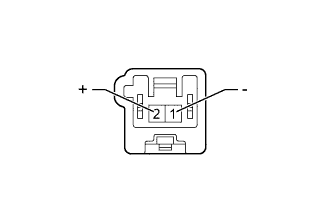
Disconnect the front No. 3 speaker assembly connector.
-
Measure the resistance according to the value(s) in the table below.
Standard Resistance Tester Connection Condition Specified Condition 1 (-) - 2 (+) Always 4.2 Ω
NG
REPLACE FRONT NO. 3 SPEAKER ASSEMBLY Click here
OK
-
-
CHECK HARNESS AND CONNECTOR (REAR NO. 2 SPEAKER - REAR SPEAKER)
-
*1: for RH Side
-
*2: for LH Side
-
Disconnect the R4*1 and/or R12*2 rear No. 2 speaker assembly connector.
-
Disconnect the R5*1 and/or R13*2 rear speaker assembly connector.
-
Measure the resistance according to the value(s) in the table below.
Standard Resistance for RH Side Tester Connection Condition Specified Condition R4-4 (+) - R5-1 Always Below 1 Ω R4-2 (-) - R5-2 Always Below 1 Ω R4-4 (+) - Body ground Always 10 kΩ or higher R4-2 (-) - Body ground Always 10 kΩ or higher for LH Side Tester Connection Condition Specified Condition R12-4 (+) - R13-1 Always Below 1 Ω R12-2 (-) - R13-2 Always Below 1 Ω R12-4 (+) - Body ground Always 10 kΩ or higher R13-2 (-) - Body ground Always 10 kΩ or higher
NG
REPAIR OR REPLACE HARNESS OR CONNECTOR
OK
-
-
INSPECT REAR SPEAKER ASSEMBLY
-
Disconnect the rear speaker assembly connector.
-
Measure the resistance according to the value(s) in the table below.
Standard Resistance for 17 Speakers Tester Connection Condition Specified Condition 1 - 2 Always 3.6 to 5.6 Ω for 12 Speakers Tester Connection Condition Specified Condition 1 - 2 Always 4.0 Ω
NG
REPLACE REAR SPEAKER ASSEMBLY Click here
OK
-
-
CHECK REAR NO. 2 SPEAKER ASSEMBLY
-
Temporarily replace the rear No. 2 speaker assembly with a new or normally functioning one Click here.
-
Check for DTCs and check if the same DTCs is output Click here.
OK No DTCs are output.
NG
INSPECT REAR NO. 3 SPEAKER ASSEMBLY Click here
OK
END (REAR NO. 2 SPEAKER ASSEMBLY IS DEFECTIVE)
-
-
INSPECT REAR NO. 3 SPEAKER ASSEMBLY
-
Disconnect the rear No. 3 speaker assembly connector.
-
Measure the resistance according to the value(s) in the table below.
Standard Resistance for 17 Speakers Tester Connection Condition Specified Condition 1 - 2 Always 4.8 to 6.8 Ω for 12 Speakers Tester Connection Condition Specified Condition 1 - 2 Always 2.5 Ω Result Result Proceed to OK (for 17 Speakers) A OK (for 12 Speakers) B NG C
B
REPLACE STEREO COMPONENT AMPLIFIER ASSEMBLY Click here
C
REPLACE REAR NO. 3 SPEAKER ASSEMBLY Click here
A
-
-
CHECK REAR HEADER SPEAKER ASSEMBLY
-
Temporarily replace the rear header speaker assembly with a new or normally functioning one Click here.
-
Check for DTCs and check if the same DTCs is output Click here.
OK No DTCs are output.
NG
REPLACE STEREO COMPONENT AMPLIFIER ASSEMBLY Click here
OK
END (REAR HEADER SPEAKER ASSEMBLY IS DEFECTIVE)
-