STEERING LINKAGE REMOVAL

Tech Tips
-
Use the same procedure for RHD and LHD vehicles.
-
The procedure listed below is for LHD vehicles.
-
PRECAUTION
Note
After turning the engine switch off, waiting time may be required before disconnecting the cable from the battery terminal. Therefore, make sure to read the disconnecting the cable from the battery terminal notice before proceeding with work Click here.
-
PLACE FRONT WHEELS FACING STRAIGHT AHEAD
-
DISCONNECT CABLE FROM NEGATIVE BATTERY TERMINAL
CAUTION:
Wait at least 90 seconds after disconnecting the cable from the negative (-) battery terminal to disable the SRS system.
Note
When disconnecting the cable, some systems need to be initialized after the cable is reconnected Click here.
-
REMOVE FRONT WHEELS
-
REMOVE ENGINE UNDER COVER
-
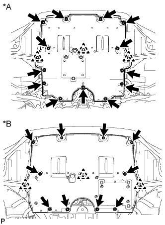
Text in Illustration *A for 2WD *B for AWD for 2WD:
Remove the 13 screws, 3 clips and engine under cover.
-
for AWD:
Remove the 10 screws, 3 clips and engine under cover.
-
-
REMOVE REAR ENGINE UNDER COVER LH (for 2WD)
-
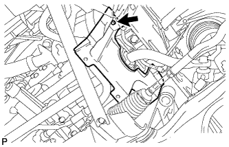
Remove the screw and rear engine under cover LH.
-
-
REMOVE REAR ENGINE UNDER COVER RH (for 2WD)
Tech Tips
Remove the RH side following the same procedure as for the LH side.
-
REMOVE FRONT SUSPENSION MEMBER BRACE (for 2WD)
-
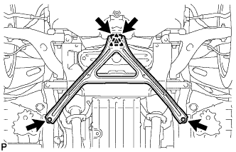
Remove the 4 bolts, and then turn the clip and remove the front suspension member brace.
Tech Tips
Do not remove the clip from the front suspension member brace.
-
-
REMOVE NO. 2 ENGINE UNDER COVER (for 2WD)
-
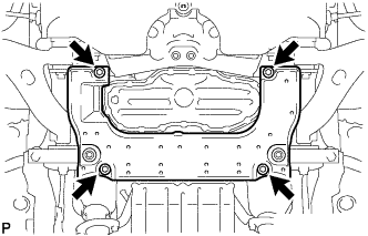
Remove the 4 screws and No. 2 engine under cover.
-
-
REMOVE FRONT SUSPENSION MEMBER LOWER PROTECTOR (for 2WD)
-
Remove the 4 bolts, and then turn the clip and remove the front suspension member brace.
Tech Tips
Do not remove the clip from the front suspension member brace.
-
-
SECURE STEERING WHEEL ASSEMBLY
-
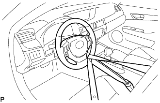
Secure the steering wheel with the seat belt in order to prevent rotation.
Tech Tips
This operation is useful to prevent damage to the spiral cable.
-
-
DISCONNECT STEERING SLIDING WITH SHAFT YOKE SUB-ASSEMBLY (for 2WD without VGRS)
-
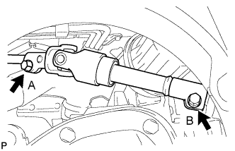
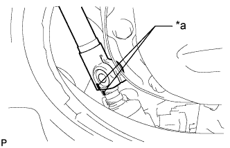
Loosen the bolt labeled A, remove the bolt labeled B.
Note
Do not remove the bolt labeled A, only loosen it.
-
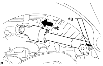
Text in Illustration *a Matchmarks *b Slide Slide the steering sliding with shaft yoke in the direction of the arrow and place matchmarks.
-
Disconnect the steering sliding with shaft yoke from the steering link.
-
-
DISCONNECT STEERING SLIDING WITH SHAFT YOKE SUB-ASSEMBLY (for 2WD with VGRS)
-
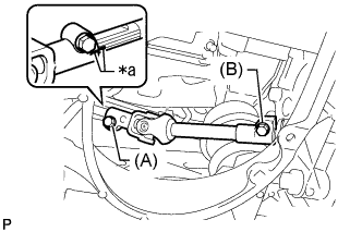
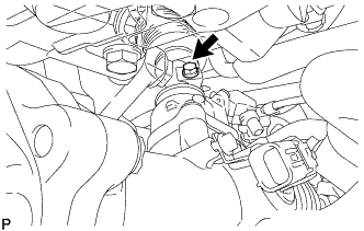
Text in Illustration *a Matchmark Loosen the bolt labeled A and remove the bolt labeled B, and then slide the steering sliding with shaft yoke sub-assembly.
Note
-
Do not remove the bolt labeled A.
-
Do not disconnect the steering sliding with shaft yoke sub-assembly from the power steering link assembly.
-
-
Put matchmark on the steering sliding with shaft yoke sub-assembly and steering actuator assembly.
-
Text in Illustration *a Matchmark Put matchmarks on the steering sliding with shaft yoke sub-assembly and power steering link assembly.
-
Disconnect the steering sliding with shaft yoke sub-assembly from the power steering link assembly.
-
Remove the bolt and steering sliding with shaft yoke sub-assembly from the steering actuator assembly.
-
-
REMOVE NO. 2 STEERING INTERMEDIATE SHAFT ASSEMBLY (for AWD)
-
Remove the bolt from the No. 2 steering intermediate shaft.
-

Text in Illustration *a Matchmarks *b Slide Slide the No. 2 steering intermediate shaft in the direction of the arrow and place matchmarks.
-
Disconnect the No. 2 steering intermediate shaft from the steering link.
-
-
REMOVE ENGINE ASSEMBLY WITH TRANSMISSION (for AWD)
-
REMOVE NO. 2 UPPER FRONT SUSPENSION MEMBER (for 2WD)
-
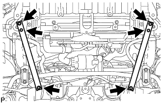
Remove the 6 bolts and front No. 2 upper suspension member.
-
-
DISCONNECT TIE ROD ASSEMBLY LH (for 2WD)
-
Remove the clip and castle nut.
-
Install 2 spacers (SST spacer B) to the tie rod assembly LH so that there is a space of approximately 1 mm (0.0397 in.) between the arm and spacers.
- SST
- 09960-20010 ( 09961-02060 )
Note
-
Be sure to install the spacers (SST spacer B) as the steering knuckle spacer may shift.
-
As SST may become damaged, make sure the space between the arm and spacers is not 1 mm (0.0397 in.) or less.
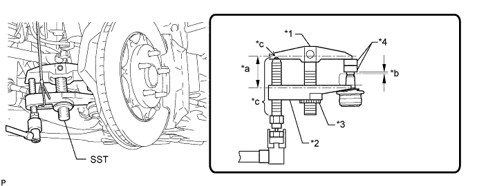
Text in Illustration *1 Body *2 Claw *3 Nut *4 Spacer B *a Parallel *b 1 mm (0.0397 in.) *c Molybdenum Grease Application Area - - -
Using SST, disconnect the tie rod assembly from the steering knuckle.
- SST
- 09960-20010 ( 09961-02060 )
CAUTION:
Apply grease molybdenum grease to the bolt threads and the tip of SST.
Note
-
Do not damage the dust cover.
-
As the dust cover may be damaged, adjust SST with the center nut so that the body and claw are parallel.
-
Make sure to tie the string of SST to the vehicle to prevent SST from dropping.
-
-
DISCONNECT TIE ROD ASSEMBLY RH (for 2WD)
Tech Tips
Use the same procedures described for the LH side.
-
DISCONNECT TIE ROD ASSEMBLY LH (for AWD)
-
Remove the clip and castle nut.
-
Install 2 spacers (SST spacer B) to the tie rod assembly LH so that there is a space of approximately 1 mm (0.0397 in.) between the arm and spacers.
- SST
- 09960-20010 ( 09961-02010 )
Note
-
Be sure to install the spacers (SST spacer B) as the steering knuckle spacer may shift.
-
As SST may become damaged, make sure the space between the arm and spacers is not 1 mm (0.0397 in.) or less.
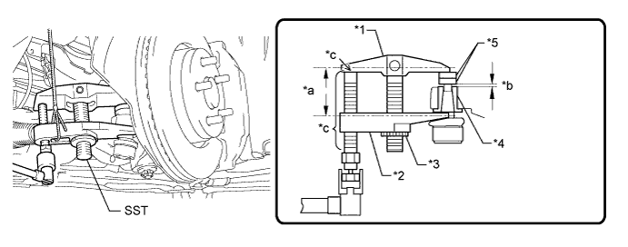
Text in Illustration *1 Body *2 Claw *3 Nut *4 Spacer *5 Spacer B - - *a Parallel *b 1 mm (0.0397 in.) *c Molybdenum Grease Application Area - - -
Using SST, disconnect the tie rod assembly from the steering knuckle.
- SST
- 09960-20010 ( 09961-02010 )
CAUTION:
Apply grease molybdenum grease to the bolt threads and the tip of SST.
Note
-
Do not damage the dust cover.
-
As the dust cover may be damaged, adjust SST with the center nut so that the body and claw are parallel.
-
Make sure to tie the string of SST to the vehicle to prevent SST from dropping.
-
If the axle carrier spacer (*4) comes out of position, replace the axle carrier.
-
-
DISCONNECT TIE ROD ASSEMBLY RH (for AWD)
Tech Tips
Use the same procedure as for the LH side.
-
REMOVE POWER STEERING LINK ASSEMBLY (for 2WD)
-
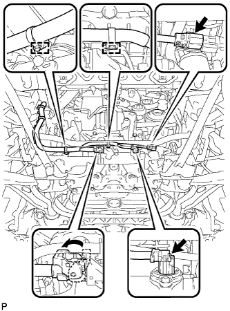
Disconnect the 2 wire harness clamps and 3 connectors, and then disconnect wire harness from the steering link assembly.
Tech Tips
Pull up the lock and release the lock lever to disconnect the connector which uses a lock.
-
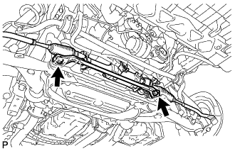
Remove the 2 bolts, No. 1 steering rack housing bracket and 2 nuts, and then remove the power steering link assembly from the suspension crossmember.
-
-
REMOVE POWER STEERING LINK ASSEMBLY (for AWD)
-
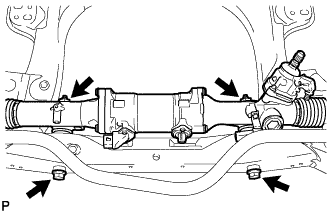
Remove the 2 bolts and 2 nuts, and then remove the power steering link assembly from the suspension crossmember.
-