DYNAMIC REAR STEERING ACTUATOR REMOVAL

-
PRECAUTION
Note
After turning the engine switch off, waiting time may be required before disconnecting the cable from the battery terminal. Therefore, make sure to read the disconnecting the cable from the battery terminal notice before proceeding with work Click here.
-
DISCONNECT CABLE FROM NEGATIVE BATTERY TERMINAL
Note
When disconnecting the cable, some systems need to be initialized after the cable is reconnected Click here.
-
REMOVE REAR WHEELS
-
REMOVE NO. 1 FLOOR UNDER COVER
-
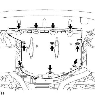
Remove the 4 clips, 6 nuts and No. 1 floor under cover.
-
-
DISCONNECT REAR STEERING TIE ROD ASSEMBLY LH
-
Remove the clip and castle nut.
-
Install 2 spacers (SST spacer B) to the tie rod assembly LH so that there is a space of approximately 1 mm (0.0397 in.) between the arm and spacers.
- SST
- 09960-20010 ( 09961-02060 )
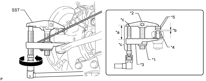
Text in Illustration *1 Nut *2 Body *3 Claw *4 Spacer *5 Spacer B - - *a Parallel *b 1 mm (0.0394 in.) *c Molybdenum Grease Application Area - - CAUTION:
Apply grease molybdenum grease to the bolt threads and the tip of SST.
Note
-
Be sure to install the spacers (SST spacer B) as the steering knuckle spacer may shift.
-
As SST may become damaged, make sure the space between the arm and spacers is not 1 mm (0.0397 in.) or less.
-
Using SST, disconnect the tie rod assembly from the steering knuckle.
Note
-
Do not damage the dust cover.
-
As the dust cover may be damaged, adjust SST with the center nut so that the body and claw are parallel.
-
Make sure to tie the string of SST to the vehicle to prevent SST from dropping.
-
If the axle carrier spacer (*4) comes out of position, replace the axle carrier and tie rod.
-
-
-
DISCONNECT REAR STEERING TIE ROD ASSEMBLY RH
Tech Tips
Use the same procedure as for the LH side.
-
REMOVE SPARE WHEEL COVER TRAY
-
REMOVE ECU BRACKET
-
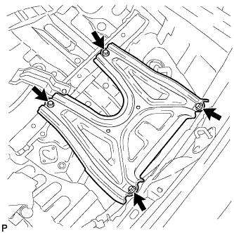
Remove the 4 bolts and ECU bracket.
-
-
REMOVE REAR STEERING LINK ASSEMBLY
-
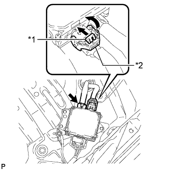
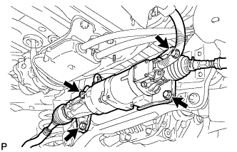
Text in Illustration *1 Lock *2 Claw Disconnect the 2 connectors from the rear steering control ECU.
Tech Tips
Pull up the lock, detach the claw and move the lever to disconnect the connector which uses a lock.
-
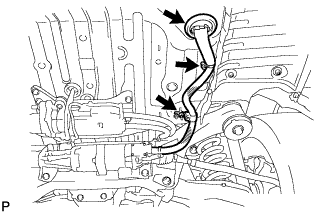
Remove the nut and detach the clamp and grommet of the wire harness.
-
Remove the 4 bolts and rear steering link assembly.
Note
Do not drop the rear steering link assembly.
-