BRAKE ACTUATOR INSTALLATION

-
INSTALL NO. 5 BRAKE ACTUATOR BRACKET
-
Install the No. 5 brake actuator bracket with the bolt.
- Torque:
- 11 N*m { 112 kgf*cm, 8 ft.*lbf }
-
-
INSTALL BRAKE ACTUATOR WITH BRACKET
-
Install the brake actuator with bracket with the 2 bolts and nut. Tighten the 2 bolts and nut uniformly in alphabetical order.
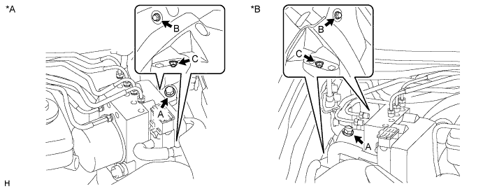
Text in Illustration *A for LHD *B for RHD - Torque:
- 19 N*m { 194 kgf*cm, 14 ft.*lbf }
Note
-
Do not damage the brake lines or wire harness.
-
Do not hold the actuator by the connector.
-
If the actuator is dropped, replace it.
-
Temporarily tighten each brake line to the correct positions of the actuator assembly with bracket as shown in the illustration.
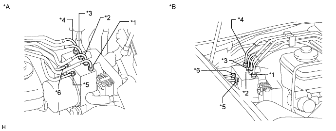
Text in Illustration *A for LHD *B for RHD Tech Tips
-
*1: to front wheel cylinder RH
-
*2: to front wheel cylinder LH
-
*3: to rear wheel cylinder RH
-
*4: to rear wheel cylinder LH
-
*5: from front master cylinder
-
*6: from rear master cylinder
-
-
Using a union nut wrench, tighten each brake line.
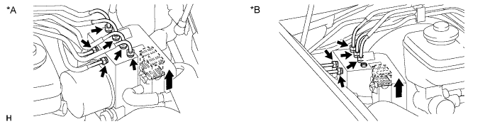
Text in Illustration *A for LHD *B for RHD - Torque:
- 15 N*m { 155 kgf*cm, 11 ft.*lbf }
Note
Use the formula to calculate special torque values for situations where a union nut wrench is combined with a torque wrench Click here.
-
Connect the brake actuator connector.
Note
-
Make sure that the connector is locked securely.
-
Make sure that the actuator connector can be connected smoothly. Do not allow water, oil or dirt to enter.
-
-
-
INSTALL BRAKE MASTER CYLINDER SUB-ASSEMBLY (for RHD)
Note
-
The master cylinder and piston are designed so that the piston can easily fall out. Prevent this by making sure that the tip of the master cylinder points downward when handling the master cylinder.
-
Make sure foreign matter does not adhere to the piston of the master cylinder. If foreign matter adheres, clean it off with a cloth. Then apply lithium soap base glycol grease to the entire outer circumference of the piston surface that contacts the booster.
-
Install a new O-ring to the master cylinder.
-
for LHD:
Install the master cylinder to the booster with the 2 nuts.
- Torque:
- 13 N*m { 127 kgf*cm, 9 ft.*lbf }
-
for RHD:
Install the harness clamp bracket and brake master cylinder with the 2 nuts.
- Torque:
- 13 N*m { 127 kgf*cm, 9 ft.*lbf }
Note
Make sure that the claw of the harness clamp bracket is securely attached to the brake master cylinder.
-
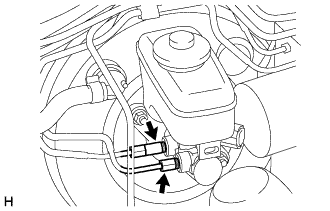
Using a union nut wrench, connect the 2 brake lines to the master cylinder.
- Torque:
- 15 N*m { 155 kgf*cm, 11 ft.*lbf }
Note
Use the formula to calculate special torque values for situations where a union nut wrench is combined with a torque wrench Click here.
-
Connect the brake fluid level warning switch connector to the brake master cylinder.
-
-
INSTALL FRONT NO. 2 BRAKE TUBE (for RHD)
-
Hold the flexible hose in place with a wrench and connect the No. 2 brake tube to the flexible hose using a union nut wrench.
- Torque:
- 15 N*m { 155 kgf*cm, 11 ft.*lbf }
Note
Use the formula to calculate special torque values for situations where a union nut wrench is combined with a torque wrench Click here.
-
Install the grommet of the No. 2 brake tube to the body.
Note
Make sure that the grommet is securely attached to the body.
-
Using a union nut wrench, connect the No. 2 brake tube to the actuator assembly.
- Torque:
- 15 N*m { 155 kgf*cm, 11 ft.*lbf }
Note
Use the formula to calculate special torque values for situations where a union nut wrench is combined with a torque wrench Click here.
-
-
CONNECT CABLE TO NEGATIVE BATTERY TERMINAL
Note
When disconnecting the cable, some systems need to be initialized after the cable is reconnected Click here.
-
BLEED BRAKE SYSTEM
CAUTION:
If air is bled without using the GTS, damage or accidents may result. Therefore, always use the GTS when bleeding air.
-
Remove the brake master cylinder reservoir filler cap assembly.
-
Add brake fluid until the fluid level is between the MIN and MAX lines of the reservoir.
-
Using a union nut wrench, disconnect the 2 brake tubes from the master cylinder.
-
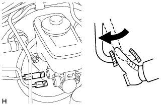
Slowly depress and hold the brake pedal.
-
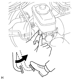
Block the tube holes with your fingers, and then release the brake pedal.
-
Remove your fingers, slowly depress and hold the brake pedal, block the tube holes with your fingers again, and then release the brake pedal. Repeat this step 3 or 4 times.
-
Using a union nut wrench, connect the 2 brake tubes to the brake master cylinder assembly.
- Torque:
- 15 N*m { 155 kgf*cm, 11 ft.*lbf }
Note
Use the formula to calculate special torque values for situations where a union nut wrench is combined with a torque wrench Click here.
-
Loosen the bleeder plug of the front brake cylinder RH.
-
Repeatedly depress the brake pedal and bleed the air from the bleeder plug of the front brake cylinder RH.
Note
Add fluid as necessary so that the fluid in the reservoir does not decrease below the MIN level.
-
After air is completely bled out, tighten the bleeder plug while depressing the brake pedal.
- Torque:
- 11 N*m { 110 kgf*cm, 8 ft.*lbf }
-
Bleed the air from the bleeder plug of the front disc brake cylinder LH using the same procedure as for the RH side.
-
Loosen the bleeder plug of the rear brake cylinder RH.
-
Repeatedly depress the brake pedal and bleed the air from the bleeder plug of the rear brake cylinder RH.
Note
Add fluid as necessary so that the fluid in the reservoir does not decrease below the MIN level.
-
After the air is completely bled out, tighten the bleeder plug while depressing the brake pedal.
- Torque:
- 8.3 N*m { 85 kgf*cm, 73 in.*lbf }
-
Bleed the air from the bleeder plug of the rear disc brake cylinder LH using the same procedure as for the RH side.
-
Depress the brake pedal more than 20 times with the engine switch off.
-
Connect the GTS to the DLC3.
-
Turn the engine switch on (IG) and turn the tester on.
Note
Do not start the engine.
-
Enter the following menus: Chassis / ABS/VSC/TRC / Utility / Air Bleeding.
-
Select and run "Inhalation" from the Air Bleeding screen on the GTS.
Note
Follow the prompts on the tester screen to bleed the air for both wheels (front and rear) on the right side.
-
Loosen the bleeder plug of the right front wheel.*1
-
Using the GTS, operate the actuator.
Tech Tips
-
To protect the actuator, the operation stops automatically.
-
Make sure the brake pedal is released.
-
-
Check the GTS screen to confirm that the operation stopped.
-
Tighten the bleeder plug.*2
-
Repeat the procedures above from *1 to *2 until the air is completely bled out.
-
Tighten the bleeder plug.
- Torque:
- 11 N*m { 110 kgf*cm, 8 ft.*lbf }
-
Bleed the air for the right rear wheel using the same procedure as for the right front wheel.
-
Select and run "Decrease" from the Air Bleeding screen on the GTS.
Note
Follow the prompts on the tester screen to bleed the air for all 4 wheels.
-
Loosen the bleeder plug of the right front wheel.*3
-
Using the GTS, operate the actuator and at the same time fully depress and hold the brake pedal.
Tech Tips
To protect the solenoids, the actuator operation stops automatically in 4 seconds. When operating the actuator repeatedly, follow the prompts on the tester screen and wait for 20 seconds or more between each operation.
Note
-
At this time, the brake pedal becomes difficult to depress. However, be sure to hold the brake pedal in the fully depressed position until brake fluid comes out of the bleeder plug.
-
Do not repeatedly depress the brake pedal; hold the brake pedal in the fully depressed position.
-
-
Tighten the bleeder plug and release the brake pedal.*4
-
Repeat the procedures above from *3 to *4 until the air is completely bled out.
-
Tighten the bleeder plug.
- Torque:
- for Front Brake
- 11 N*m { 110 kgf*cm, 8 ft.*lbf }
- for Rear Brake
- 8.3 N*m { 85 kgf*cm, 73 in.*lbf }
-
Bleed the air for the other 3 wheels using the same procedure as for the right front wheel.
-
Repeat the procedure in which air is bled from the brake line by repeatedly depressing the brake pedal.
Note
Repeat this step for each wheel until air is completely bled out.
-
Check for brake fluid leaks.
-
Check the fluid level in the reservoir Click here.
-
-
INSTALL FRONT WHEEL
- Torque:
- 103 N*m { 1050 kgf*cm, 76 ft.*lbf }
-
INSTALL ENGINE ROOM SIDE COVER LH
-
Attach the 2 clips to install the engine room side cover LH.
-
-
INSPECT BRAKE ACTUATOR WITH GTS
-
PERFORM YAW RATE AND ACCELERATION SENSOR ZERO POINT CALIBRATION