WINDSHIELD GLASS REMOVAL

Tech Tips
-
Use the same procedure for RHD and LHD vehicles.
-
The procedure listed below is for LHD vehicles.
-
PRECAUTION
Note
After turning the engine switch off, waiting time may be required before disconnecting the cable from the battery terminal. Therefore, make sure to read the disconnecting the cable from the battery terminal notice before proceeding with work Click here.
-
DISCONNECT CABLE FROM NEGATIVE BATTERY TERMINAL
CAUTION:
Wait at least 90 seconds after disconnecting the cable from the negative (-) battery terminal to disable the SRS system.
Note
When disconnecting the cable, some systems need to be initialized after the cable is reconnected Click here.
-
REMOVE WINDSHIELD OUTSIDE MOULDING LH
-
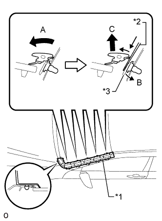
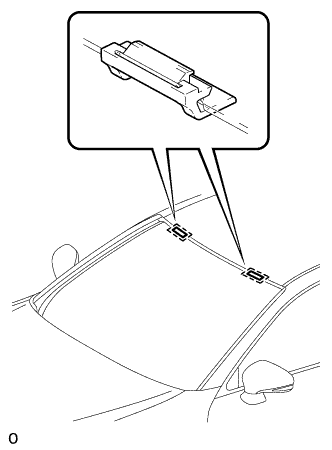
Text in Illustration *1 Protective Tape *2 Moulding Remover B *3 No. 1 Windshield Outside Moulding Clip Put protective tape around the windshield outside moulding LH.
-
Move the windshield outside moulding LH in the direction indicated by the arrow labeled A in the illustration to widen the space between the moulding and body.
-
Insert moulding remover B between the windshield outside moulding LH and No. 1 windshield outside moulding clip.
-
While pushing the claw of the No. 1 windshield outside moulding clip in the direction indicated by the arrow labeled B in the illustration, pull the windshield outside moulding LH upward in the direction indicated by the arrow labeled C in the illustration to detach the 4 claws and remove the moulding.
Note
-
When removing the windshield outside moulding LH, be careful not to damage the No. 1 windshield outside moulding clip.
-
If a No. 1 windshield outside moulding clip is damaged or becomes detached from the vehicle, replace it with a new one.
-
-
-
REMOVE WINDSHIELD OUTSIDE MOULDING RH
Tech Tips
Use the same procedure described for the LH side.
-
REMOVE CENTER ROOF DRIP SIDE FINISH MOULDING LH
-
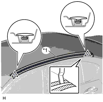
Text in Illustration *1 Protective Tape Put protective tape around the center roof drip side finish moulding.
-
Using a moulding remover, detach the 2 clips and remove the center roof drip side finish moulding.
Note
-
When removing the center roof drip side finish moulding, be careful not to damage the No. 1 roof drip side finish moulding clips.
-
If a No. 1 roof drip side finish moulding clip is damaged or becomes detached from the vehicle, replace it with a new one.
-
-
-
REMOVE CENTER ROOF DRIP SIDE FINISH MOULDING RH
Tech Tips
Use the same procedure described for the LH side.
-
REMOVE NO. 1 WINDSHIELD OUTSIDE MOULDING CLIP
Tech Tips
Perform the following procedures if replacing any No. 1 windshield outside moulding clip(s).
-
Using a moulding remover B, remove the No. 1 windshield outside moulding clip.
-
-
REMOVE NO. 3 WINDSHIELD OUTSIDE MOULDING CLIP
Tech Tips
Perform the following procedures if replacing any No. 3 windshield outside moulding clip(s).
-
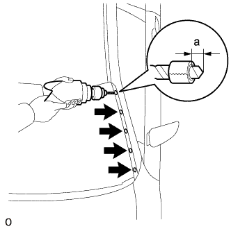
Put a 4 mm (0.157 in.) drill bit into a drill.
OK Area Specified Condition a 5.0 mm -
Wind tape around the drill bit approximately 5 mm (0.197 in.) from the tip of the drill.
Tech Tips
Tape the 5 mm (0.157 in.) drill bit to prevent the drill bit from going too deep.
-
Lightly press the drill against the clip, drill off the flanges of the clip, and remove the No. 1 windshield outside moulding clip.
CAUTION:
Be careful as the drilled clip may become hot.
Note
-
Pressing the drill too firmly will cause the clip to turn and result in the clip not being drilled through.
-
Do not pry the clip with the drill because this may cause damage to the installation holes of the clip or the drill bit.
-
-
Remove the No. 3 windshield outside moulding clip.
-
-
REMOVE FRONT WIPER ARM AND BLADE ASSEMBLY RH
-
Remove the nut and the front wiper arm and blade assembly RH.
-
-
REMOVE FRONT WIPER ARM AND BLADE ASSEMBLY LH
-
Remove the nut and the front wiper arm and blade assembly LH.
-
-
REMOVE ENGINE ROOM SIDE COVER
-
Remove the 2 clips.
-
Remove the guide and the engine room side cover.
-
-
REMOVE COWL TOP VENTILATOR LOUVER SUB-ASSEMBLY
-
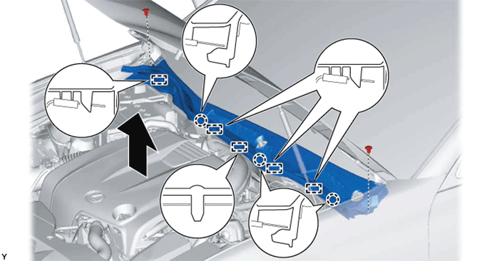
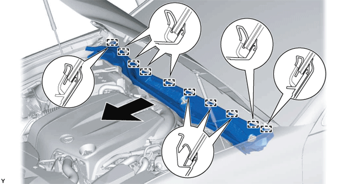
Disengage the claw, and remove the outside windshield moulding from the cowl top ventilator louver sub-assembly.
-
Remove the 2 clips.
-
Disengage the 3 claws and 5 guides as shown in the illustration.
-
Disengage the 10 guides and pull out the cowl top ventilator louver sub-assembly as shown in the illustration.
-
-
REMOVE FRONT DOOR SCUFF PLATE LH
-
Place your hands on the inner portion of the front door scuff plate LH and detach the 2 claws labeled A, 6 claws labeled B and 2 claws labeled C in the order shown in the illustration.
-
Raise the front door scuff plate LH to detach the 4 clips on the outer side and remove it.
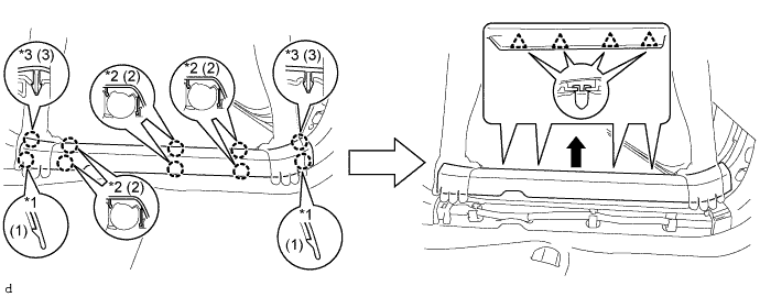
Text in Illustration *1 Claw A *2 Claw B *3 Claw C - -
-
-
REMOVE FRONT DOOR SCUFF PLATE RH
Tech Tips
Use the same procedure described for the LH side.
-
REMOVE FRONT DOOR OPENING TRIM COVER LH
-
Detach the 5 claws and remove the front door opening trim cover LH.
-
-
REMOVE FRONT DOOR OPENING TRIM COVER RH
Tech Tips
Use the same procedure described for the LH side.
-
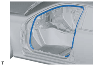
REMOVE FRONT DOOR OPENING TRIM WEATHERSTRIP LH
-
Remove the front door opening trim weatherstrip LH.
Tech Tips
Remove any remaining sealer from the vehicle body.
-
-
REMOVE FRONT DOOR OPENING TRIM WEATHERSTRIP RH
Tech Tips
Use the same procedure described for the LH side.
-
REMOVE FRONT PILLAR GARNISH LH
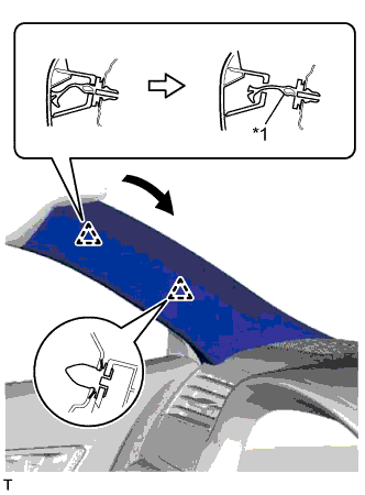
Text in Illustration *1 Front Pillar Garnish Clip
-
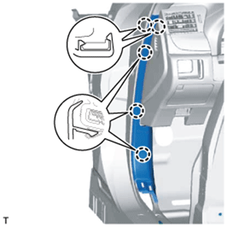
Pull the upper part of the garnish toward the inside of the cabin and detach the 2 clips.
Tech Tips
Make the front pillar garnish LH hang down from the front pillar garnish clip.
-
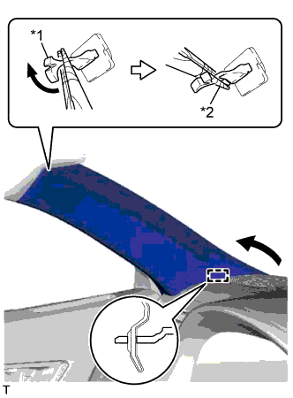
Text in Illustration *1 Front Pillar Garnish Clip *2 Protective Tape Turn the end of the front pillar garnish clip 90° with needle-nose pliers and remove it from the front pillar garnish LH.
Note
-
Front pillar garnish clips are reusable if they are not removed from the vehicle and have no damage.
-
Replace the front pillar garnish clips with new ones if they are removed from the vehicle.
Tech Tips
Tape the tips of the needle-nose pliers before use.
-
-
Detach the guide and remove the front pillar garnish LH.
-
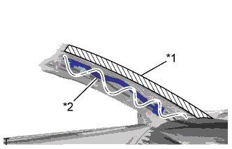
Text in Illustration *1 Adhesive Tape *2 Protective Cover Protect the curtain shield airbag assembly.
-
Completely cover the airbag with a cloth or nylon sheet and secure the ends of the cover with adhesive tape as shown in the illustration.
Note
Cover the curtain shield airbag with a protective cover as soon as the front pillar garnish is removed.
-
-
-
REMOVE FRONT PILLAR GARNISH RH
Tech Tips
Use the same procedure described for the LH side.
-
REMOVE FRONT ROOF TOP GARNISH
-
w/ Night View System:
-
Using a moulding remover, detach the 2 claws A.
-
Using a moulding remover, detach the 2 clips A.
Tech Tips
When the 2 clips A are detached, claw B, guide B and the fastener may also become detached.
-
Detach the 2 clips B.
-
Move the hooks of the 2 guides A forward, disconnect the connector, and remove the front roof garnish together with the map light assembly.
Note
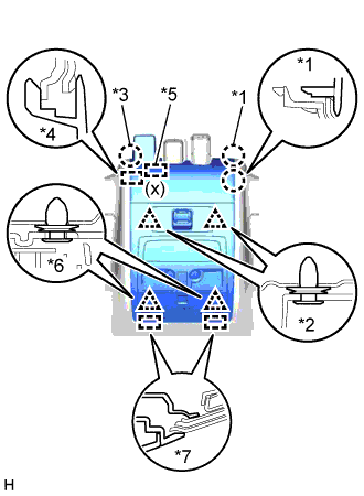
When removing and installing the front roof top garnish, do not apply force to the camera sensor located at (x).
Tech Tips
If the claw B, guide B, and fastener do not become detached when the 2 clips labeled A are detached, detach claw B, guide B and the fastener to remove the front roof top garnish together with the map light assembly.
-
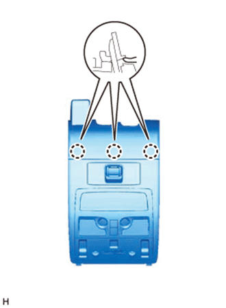
Text in Illustration *1 Claw A *2 Clip A *3 Claw B *4 Guide B *5 Fastener *6 Clip B *7 Guide A Detach the 3 claws on the back of the front roof top garnish and map light assembly, and disconnect the front roof top garnish and map light assembly.
-
-
w/o Night View System:
-
Using a moulding remover, detach the 2 claws A.
-
Using a moulding remover, detach the 2 clips A.
Tech Tips
When the 2 clips A are detached, claw B and guide B may also become detached.
-
Detach the 2 clips B.
-
Move the hooks of the 2 guides A forward, disconnect the connector, and remove the front roof garnish together with the map light assembly.
Note
w/ Lane Keeping Assist System:
When removing and installing the front roof top garnish, do not apply force to the camera sensor located at (x).
Tech Tips
If the claw B and guide B do not become detached when the 2 clips labeled A are detached, detach claw B and guide B to remove the front roof top garnish together with the map light assembly.
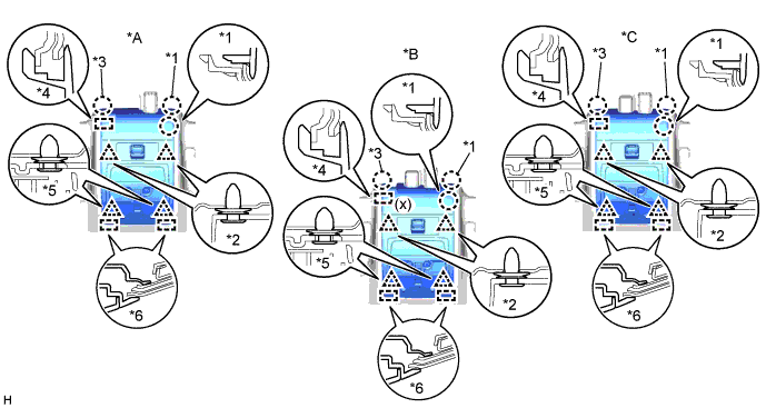
Text in Illustration *A for Standard *B w/ Lane Keeping Assist System *C w/ Rain Sensor - - *1 Claw A *2 Clip A *3 Claw B *4 Guide B *5 Clip B *6 Guide A -
Detach the 3 claws on the back of the front roof top garnish and map light assembly, and disconnect the front roof top garnish and map light assembly.
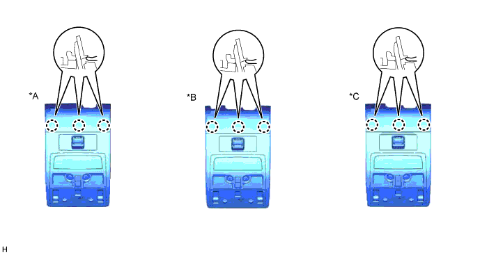
Text in Illustration *A for Standard *B w/ Lane Keeping Assist System *C w/ Rain Sensor - -
-
-
-
REMOVE MAP LIGHT ASSEMBLY
-
Using a moulding remover, detach the 2 claws A.
-
Using a moulding remover, detach the 2 clips A.
Tech Tips
When the 2 clips A are detached, claw B and guide B may also become detached.
-
Detach the 2 clips B.
-
Move the hooks of the 2 guides forward, disconnect the connector, and remove the map light assembly together with the front roof top garnish.
Note
w/ Lane Keeping Assist System:
When removing the map light assembly together with the front roof top garnish, make sure not to apply excessive pressure to the camera sensor (x).
Tech Tips
If claw B and guide B do not become detached when the 2 clips labeled A are detached, detach claw B and guide B to remove the map light assembly together with the front roof top garnish.
Text in Illustration *A for Standard *B w/ Lane Keeping Assist System *C w/ Rain Sensor - - *1 Claw A *2 Clip A *3 Claw B *4 Guide B *5 Clip B *6 Guide A -
Detach the 3 claws on the back of the map light assembly and front roof top garnish, and disconnect the map light assembly and front roof top garnish.
Text in Illustration *A for Standard *B w/ Lane Keeping Assist System *C w/ Rain Sensor - -
-
-
REMOVE INNER REAR VIEW MIRROR ASSEMBLY
-
REMOVE RAIN SENSOR (w/ Rain Sensor)
-
REMOVE VISOR BRACKET COVER
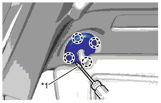
Text in Illustration *1 Protective Tape Tech Tips
Use the same procedure for both visor bracket covers.
-
Using a screwdriver, detach the 4 claws and remove the visor bracket cover.
-
-
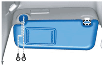
REMOVE VISOR ASSEMBLY LH
-
Detach the guide.
-
Remove the 2 screws and visor assembly LH.
-
-
REMOVE VISOR ASSEMBLY RH
Tech Tips
Use the same procedure described for the LH side.
-
REMOVE VISOR HOLDER
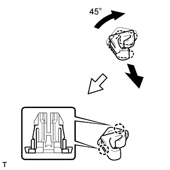
Tech Tips
Use the same procedure for both visor holders.
-
Turn the visor holder clockwise approximately 45° and pull it out as shown in the illustration.
-
Detach the 2 claws and remove the visor holder.
-
-
REMOVE ASSIST GRIP SUB-ASSEMBLY
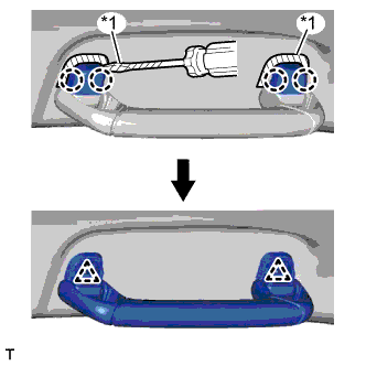
Text in Illustration *1 Protective Tape Tech Tips
Use the same procedure for both assist grips.
-
Put protective tape around the assist grip covers.
-
Using a screwdriver, detach the 4 claws and remove the 2 assist grip covers.
-
Detach the 2 clips and remove the assist grip sub-assembly.
-
Remove the 2 clips from the vehicle body.
-
-
REMOVE ROOF HEADLINING ASSEMBLY
-
Partially remove the roof headlining assembly.
Tech Tips
It is not necessary to completely remove the roof headlining. Slightly lower the front section of the roof headlining so that the windshield glass can be removed in a later step.
Refer to the following procedures Click here.
-
-
REMOVE LANE RECOGNITION CAMERA SENSOR ASSEMBLY (w/ Lane Keeping Assist System)
-
REMOVE AIR CONDITIONING THERMISTOR ASSEMBLY
-
REMOVE WINDSHIELD GLASS
-
w/ Windshield Deicer:
-
Detach the connector.
-
-
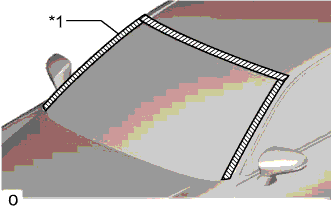
Text in Illustration *1 Protective Tape Apply protective tape to the outer surface of the vehicle body to prevent scratches.
-
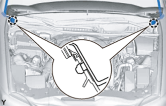
Text in Illustration *1 Matchmark Place matchmarks over the glass and vehicle body on the locations indicated in the illustration.
Tech Tips
Matchmarks do not need to be placed if not reusing the glass.
-
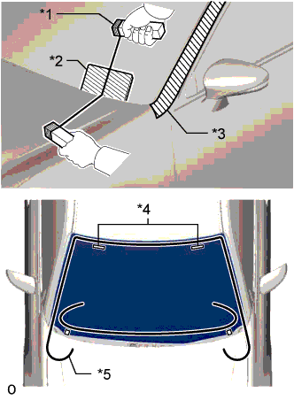
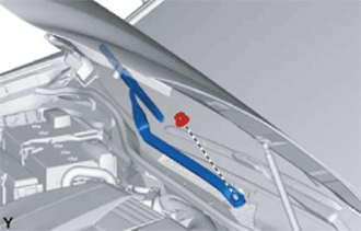
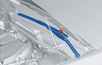
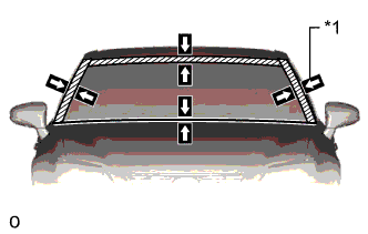
Text in Illustration *1 Handles *2 Plastic Sheet *3 Protective Tape *4 Stopper *5 Piano Wire From the interior, insert a piano wire between the vehicle body and glass as shown in the illustration.
-
Tie objects that can serve as handles (for example, wooden blocks) to both wire ends.
Note
-
When separating the glass from the vehicle, be careful not to damage the vehicle's paint or interior / exterior ornaments.
-
To prevent the instrument panel from being scratched when removing the glass, place a plastic sheet between the piano wire and instrument panel.
-
-
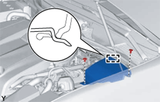
Using suction cups, detach the 2 windshield glass stoppers, 2 windshield retainers and remove the windshield glass.
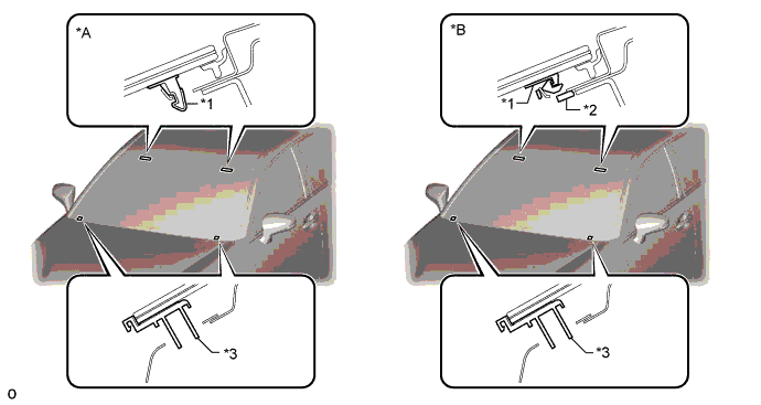
Text in Illustration *A for 1-piece Type *B for 2-piece Type *1 No. 1 Windshield Glass Stopper *2 No. 2 Windshield Glass Stopper *3 Windshield Retainer - -
-
-
-
REMOVE NO. 1 WINDSHIELD GLASS STOPPER
-
Remove the 2 No. 1 windshield stoppers.
Note
Be sure to replace the No. 1 stoppers with new ones.
-