DYNAMIC RADAR CRUISE CONTROL SYSTEM Distance Control Switch Circuit
DESCRIPTION
The distance control switch sets the vehicle-to-vehicle distance mode. The distance control switch is installed in the steering pad switch with modulator (distance control switch). The vehicle-to-vehicle distance set value can be changed by operating the steering pad switch while the dynamic radar cruise control system is in operation.
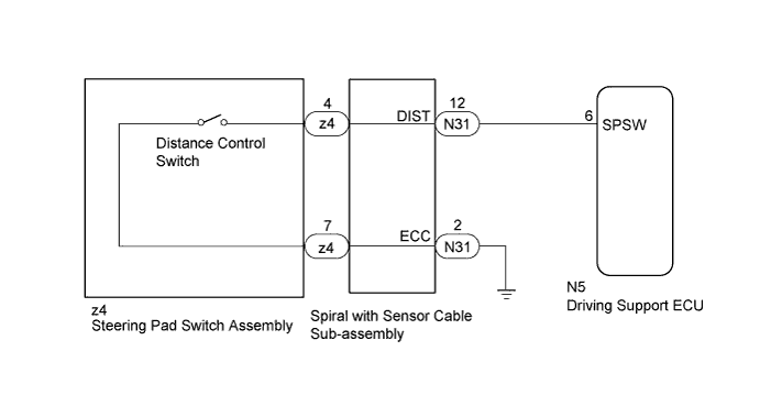
WIRING DIAGRAM
INSPECTION PROCEDURE
Note
When replacing the driving support ECU, always replace it with a new one and be sure to perform initialization Click here. If an ECU which was installed to another vehicle is used, the information stored in the ECU will not match the information from the vehicle, and as a result, a DTC may be stored.
PROCEDURE
-
READ VALUE USING GTS (DISTANCE CONTROL SWITCH)
-
Check the Data List for proper functioning of the distance control switch Click here.
Radar Cruise Tester Display Measurement Item/Range Normal Condition Diagnostic Note Distance Control Switch Distance control switch signal / ON or OFF ON: Distance control switch is on
OFF: Distance control switch is off
- OK Display changes according to steering pad switch with modulator (distance control switch) operation described in above table.
NG 
INSPECT STEERING PAD SWITCH ASSEMBLY Click here
OK 
PROCEED TO NEXT CIRCUIT INSPECTION SHOWN IN PROBLEM SYMPTOMS TABLE Click here
-
-
INSPECT STEERING PAD SWITCH ASSEMBLY
-
Remove the steering pad switch assembly Click here.
-
Inspect the steering pad switch assembly Click here.
NG 
REPLACE STEERING PAD SWITCH ASSEMBLY Click here
OK 
-
-
INSPECT SPIRAL WITH SENSOR CABLE SUB-ASSEMBLY
-
Remove the spiral with sensor cable sub-assembly Click here.
-
Inspect the spiral with sensor cable sub-assembly Click here.
NG
REPLACE SPIRAL WITH SENSOR CABLE SUB-ASSEMBLY Click here
OK
-
-
CHECK HARNESS AND CONNECTOR (SPIRAL WITH SENSOR CABLE SUB-ASSEMBLY - DRIVING SUPPORT ECU AND BODY GROUND)
-
Disconnect the N31 spiral with sensor cable sub-assembly connector.
-
Disconnect the N5 driving support ECU connector.
-
Measure the resistance according to the value(s) in the table below.
Standard Resistance Tester Connection Condition Specified Condition N31-12 (DIST) - N5-6 (SPSW) Always Below 1 Ω N31-2 (ECC) - Body ground N31-12 (DIST) - Body ground Always 10 kΩ or higher
NG
REPAIR OR REPLACE HARNESS OR CONNECTOR
OK
REPLACE DRIVING SUPPORT ECU Click here
-