OIL PUMP REMOVAL

-
REMOVE ENGINE ASSEMBLY
-
REMOVE ENGINE WIRE
-
REMOVE FUEL PUMP ASSEMBLY (for High Pressure)
-
REMOVE V-RIBBED BELT TENSIONER ASSEMBLY
-
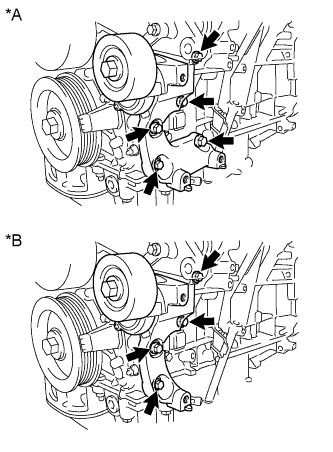
Text in Illustration *A for 2WD *B for AWD for 2WD:
Remove the 5 bolts, then remove the V-ribbed belt tensioner assembly.
-
for AWD:
Remove the 4 bolts, then remove the V-ribbed belt tensioner assembly.
-
-
REMOVE NO. 2 IDLER PULLEY SUB-ASSEMBLY
-
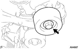
Remove the bolt, No. 2 idler pulley cover plate and No. 2 idler pulley sub-assembly.
-
-
REMOVE WATER PUMP PULLEY
-
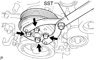
Using SST, hold the water pump pulley.
- SST
- 09960-10010 ( 09962-01000, 09963-00700 )
-
Remove the 4 bolts and water pump pulley.
-
-
REMOVE NO. 1 ENGINE COVER
-
Remove the 3 clips, then remove the No. 1 engine cover.
-
-
REMOVE INJECTOR DRIVER
-
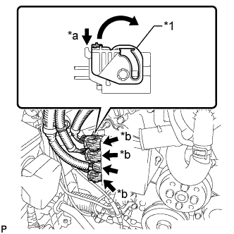
Text in Illustration *1 Lock Lever *a Release *b Lock with Connector Move the lock levers in the direction indicated by the arrow to release the 3 connector locks. Disconnect the 4 connectors from the injector driver.
-
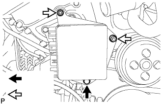
Remove the bolt, 2 nuts and injector driver.
Note
Be careful not to drop or strike the injector driver.
-
-
REMOVE NO. 2 ENGINE COVER
-
Remove the 3 clips and clamp, then remove the No. 2 engine cover.
-
-
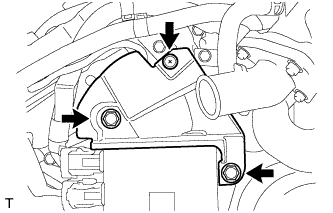
REMOVE WATER INLET ASSEMBLY
-

Disconnect the 5 hoses.
-

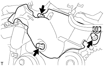
Remove the 4 bolts, nut and water inlet assembly.
Text in Illustration 
Bolt 
Nut -

Text in Illustration *1 No. 1 Water Inlet Housing Gasket *2 Water Outlet Pipe O-ring Remove the No. 1 water inlet housing gasket and water outlet pipe O-ring.
-
-
REMOVE CRANKSHAFT PULLEY
-

Text in Illustration *a Hold *b Turn Using SST, loosen the pulley bolt.
- SST
- 09213-70011 ( 09213-70020 )
- 09330-00021
-

Text in Illustration *a Hold *b Turn Tighten the pulley bolt to 2 or 3 threads of the crankshaft.
-
Using SST, remove the pulley bolt and pulley.
- SST
- 09950-50013 ( 09951-05010, 09952-05010, 09953-05020, 09954-05021 )
Tech Tips
Apply grease to the threads and tip of SST (center bolt) prior to use.
-
-
REMOVE NO. 2 OIL PAN SUB-ASSEMBLY
-
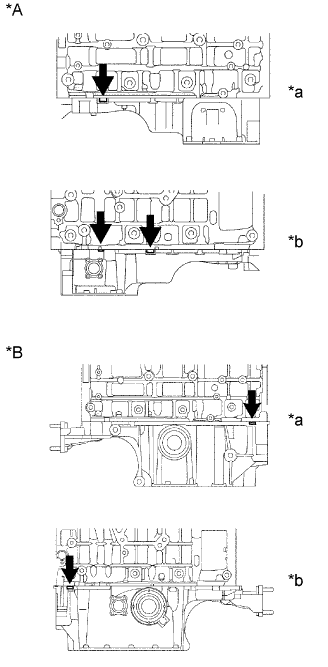
for 2WD:
Remove the 15 bolts and 2 nuts.
Text in Illustration Bolt Nut -
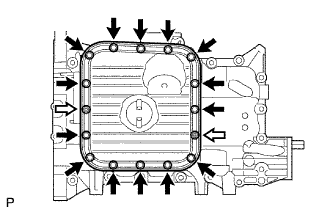
for AWD:
Remove the 14 bolts and 2 nuts.
Text in Illustration Bolt Nut -
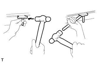
Insert the blade of oil pan seal cutter between the oil pans. Cut through the applied sealer and remove the No. 2 oil pan sub-assembly.
Note
Be careful not to damage the contact surfaces of the oil pans.
-
-
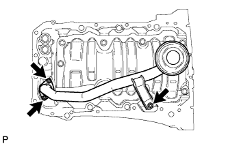
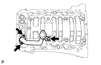
REMOVE OIL WITH STRAINER PIPE SUB-ASSEMBLY (for AWD)
-
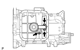
Remove the 3 nuts, oil with strainer pipe and gasket.
-
-
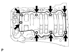
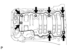
REMOVE OIL PAN SUB-ASSEMBLY
-
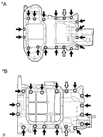
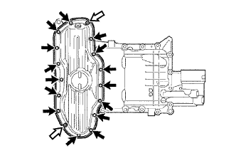
Text in Illustration *A for 2WD *B for AWD Remove the 16 bolts and 2 nuts.
Tech Tips
Be sure to clean the bolts and stud bolts and check the threads for cracks or other damage.
-
Text in Illustration *A for 2WD *B for AWD *a LH Side *b RH Side Remove the oil pan by prying between the oil pan and cylinder block with a screwdriver.
Note
Be careful not to damage the contact surfaces of the cylinder block and oil pan.
Tech Tips
Tape the screwdriver tip before use.
-
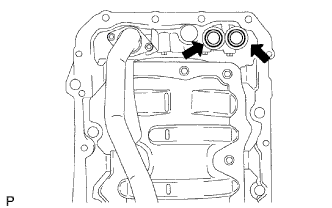
Remove the 2 O-rings.
-
-
REMOVE OIL STRAINER SUB-ASSEMBLY
-
for 2WD:
-
Remove the 3 nuts, oil strainer and gasket.
-
Remove the 8 bolts and baffle plate.
-
-
for AWD:
-
Remove the bolt, 2 nuts, oil strainer and gasket.
-
Remove the 7 bolts and baffle plate.
-
-
-
REMOVE IGNITION COIL ASSEMBLY
-
Remove the 2 nuts and disconnect the wire harness.
-
Disconnect the wire harness clamp.
-
Remove the 2 bolts and disconnect the 2 wire harness brackets.
-
Disconnect the 6 ignition coil connectors.
-
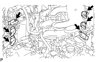
Remove the 6 bolts and the 6 ignition coil assemblies.
-
-
REMOVE NO. 1 OIL PIPE
-
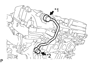
Text in Illustration *1 Oil Pipe Union *2 Oil Check Valve Bolt Remove the oil check valve bolt, oil pipe union and No. 1 oil pipe.
-
Remove the oil control valve filter LH and gaskets.
-
-
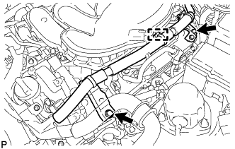
REMOVE NO. 2 OIL PIPE
-
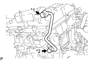
Text in Illustration *1 Oil Pipe Union *2 Oil Check Valve Bolt Remove the oil check valve bolt, oil pipe union and No. 2 oil pipe.
-
Remove the oil control valve filter RH and gaskets.
-
-
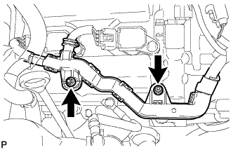
REMOVE FUEL TUBE SUB-ASSEMBLY
-
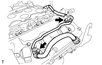
Remove the 2 bolts and fuel tube sub-assembly.
-
-
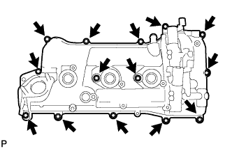
REMOVE CYLINDER HEAD COVER SUB-ASSEMBLY LH
-
Text in Illustration *1 Baffle Plate Remove the 12 bolts, head cover sub-assembly LH and gasket.
Note
The baffle plate is located on the back of the portion shown in the illustration. Do not damage the baffle plate when removing the head cover.
-
Remove the 3 gaskets.
-
-
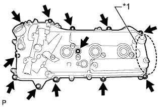
REMOVE CYLINDER HEAD COVER SUB-ASSEMBLY
-
Remove the 14 bolts, head cover sub-assembly and gasket.
-
Remove the 3 gaskets.
-
-
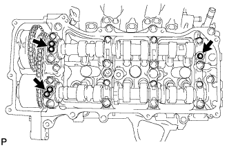
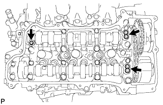
REMOVE SPARK PLUG TUBE GASKET
-
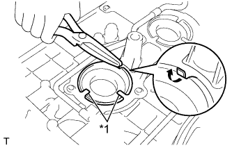
Text in Illustration *1 Claw Pry up the claws of the ventilation baffle plate.
Note
Do not deform the claws of the baffle plate more than necessary.
-
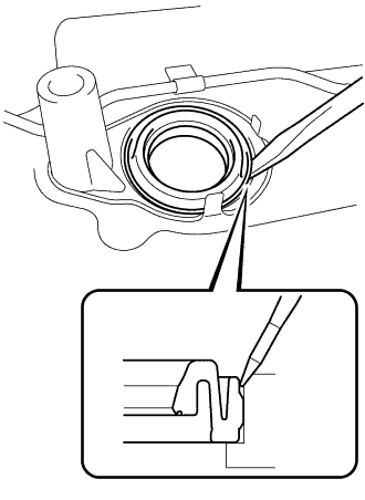
Using a screwdriver as shown in the illustration, deform each spark plug tube gasket inwards and remove the 6 spark plug tube gaskets from the the cylinder head cover.
Note
-
As much as possible prevent the plug tube gaskets from being deformed. The removed gaskets will be used when reinstalling the gaskets.
-
Do not damage the connection of the cylinder head cover.
-
Make sure not to damage the spark plug tube gasket and cylinder head cover when inserting the screwdriver in the joint area.
Tech Tips
If the cylinder head cover is damaged, smooth the surface with 400-grit sandpaper.
-
-
-
REMOVE TIMING CHAIN COVER SUB-ASSEMBLY
-
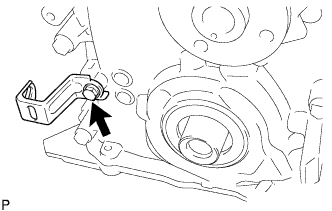
Remove the bolt and wire harness clamp bracket.
-
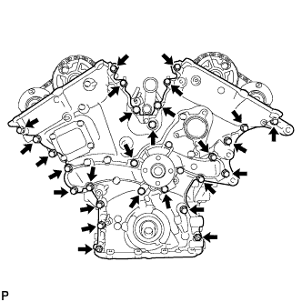
Remove the 25 bolts and 2 nuts shown in the illustration.
-
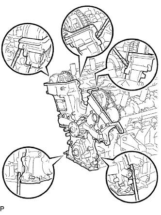
Remove the timing chain cover by prying between the timing chain cover and cylinder head or cylinder block with a screwdriver.
Note
Be careful not to damage the contact surfaces of the cylinder head, cylinder block and chain cover.
Tech Tips
Tape the screwdriver tip before use.
-
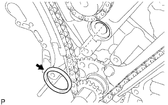
Remove the gasket.
-
-
REMOVE TIMING CHAIN CASE OIL SEAL
-
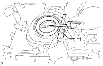
Text in Illustration *1 Wooden Block Using a screwdriver, pry out the oil seal.
Tech Tips
Tape the screwdriver tip before use.
-