ENGINE ASSEMBLY REMOVAL

CAUTION:
As the engine assembly with transmission is extremely heavy, the engine lifter may suddenly drop if the instructions listed in the repair manual are not followed. Therefore, always follow the instructions listed in the repair manual when performing this procedure.
-
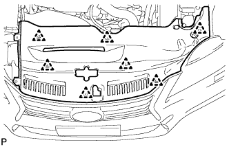
REMOVE ENGINE ROOM SIDE COVER
-
Remove the 4 clips and engine room side cover.
-
-
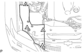
REMOVE COOL AIR INTAKE DUCT SEAL
-
Remove the 7 clips and cool air intake duct seal.
-
-
REMOVE V-BANK COVER SUB-ASSEMBLY
-
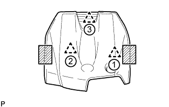
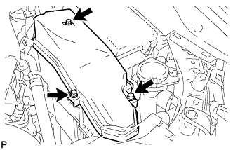
Place both hands on the sides of the cover as shown in the illustration, lift the cover to detach the 2 clips near the front in the order shown in the illustration, and then lift the cover further to detach the rear clip and remove the cover.
Text in Illustration 
Areas to place hands when lifting cover Note
If the cover is lifted rearward or forward and to the right or left at the same time, the cover maybe damaged.
-
-
DISCHARGE REFRIGERANT FROM REFRIGERATION SYSTEM
-
DISCHARGE FUEL SYSTEM PRESSURE
-
PLACE FRONT WHEELS FACING STRAIGHT AHEAD
-
PRECAUTION
Note
After turning the engine switch off, waiting time may be required before disconnecting the cable from the battery terminal. Therefore, make sure to read the disconnecting the cable from the battery terminal notice before proceeding with work Click here.
-
DISCONNECT CABLE FROM NEGATIVE BATTERY TERMINAL
Note
When disconnecting the cable, some systems need to be initialized after the cable is reconnected Click here.
-
REMOVE FRONT WHEEL
-
REMOVE ENGINE UNDER COVER
-
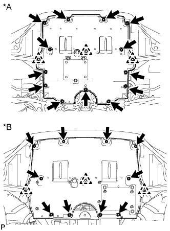
Text in Illustration *A for 2WD *B for AWD for 2WD:
Remove the 13 screws, 3 clips and engine under cover.
-
for AWD:
Remove the 10 screws, 3 clips and engine under cover.
-
-
REMOVE REAR ENGINE UNDER COVER LH (for 2WD)
-
Remove the screw and rear engine under cover LH.
-
-
REMOVE REAR ENGINE UNDER COVER RH (for 2WD)
Tech Tips
Remove the RH side following the same procedure as for the LH side.
-
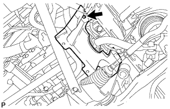
REMOVE FRONT SUSPENSION MEMBER BRACE (for 2WD)
-
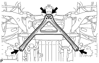
Remove the 4 bolts, and then turn the clip and remove the front suspension member brace.
Tech Tips
Do not remove the clip from the front suspension member brace.
-
-
REMOVE NO. 2 ENGINE UNDER COVER (for 2WD)
-
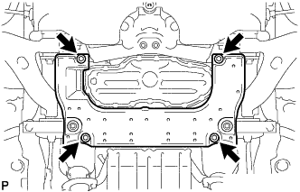
Remove the 4 screws and No. 2 engine under cover.
-
-
DRAIN ENGINE OIL
-
Remove the oil filler cap.
-
Remove the drain plug and gasket.
-
Install a new gasket and the drain plug.
- Torque:
- 40 N*m { 408 kgf*cm, 30 ft.*lbf }
-
-
DRAIN ENGINE COOLANT
-
Loosen the radiator drain cock plug and drain the coolant.
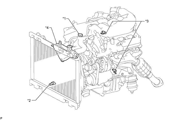
Text in Illustration *1 Radiator Cap *2 Radiator Drain Cock Plug *3 Cylinder Block Drain Cock Plug *4 Radiator Reservoir Tank CAUTION:
Do not remove the radiator cap, cylinder block drain cock plugs and radiator drain cock plug while the engine and radiator are still hot. Pressurized, hot engine coolant and steam may be released and cause serious burns.
Tech Tips
Collect the coolant in a container and dispose of it according to the local regulations.
-
Remove the radiator cap.
-
Loosen the 2 cylinder block drain cock plugs.
-
-
DRAIN DIFFERENTIAL OIL (for AWD)
-
Stop the vehicle on a level place.
-
for Front Differential:
-
Remove the engine under cover.
-
Remove the filler plug and gasket.
-
Remove the drain plug and gasket, and drain the oil.
-
Install a new gasket and the drain plug.
- Torque:
- 39 N*m { 400 kgf*cm, 29 ft.*lbf }
-
-
for Rear Differential:
-
Using a 10 mm hexagon wrench, remove the filler plug and gasket.
Text in Illustration *A for 2GR-FSE *B for 4GR-FSE -
Using a 10 mm hexagon wrench, remove the drain plug and gasket, and drain the oil.
Text in Illustration *A for 2GR-FSE *B for 4GR-FSE -
Install a new gasket and the drain plug.
- Torque:
- 49 N*m { 500 kgf*cm, 36 ft.*lbf }
-
-
-
DRAIN AUTOMATIC TRANSMISSION FLUID
-
for 2WD Click here
-
for AWD Click here
-
-
REMOVE NO. 1 AIR CLEANER INLET
-
Remove the bolt and No. 1 air cleaner inlet.
-
-
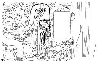
REMOVE AIR CLEANER CAP WITH AIR CLEANER HOSE
-
Disconnect the mass air flow meter connector.
-
Disconnect the clamp from the air cleaner.
-
Disconnect the VSV hose.
-
for RHD:
Disconnect the union to check valve hose.
-
Disconnect the 4 clamps.
-
Remove the hose clamp and air cleaner cap with air cleaner hose.
-
-
REMOVE AIR CLEANER FILTER ELEMENT SUB-ASSEMBLY
-
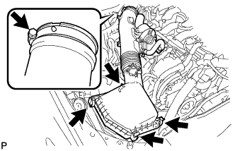
REMOVE AIR CLEANER CASE SUB-ASSEMBLY
-
Remove the 2 bolts, 2 clamps and air cleaner case sub-assembly.
Note
When removing the air cleaner case sub-assembly, be careful not to lose the grommet on the underside of the air cleaner case.
-
-
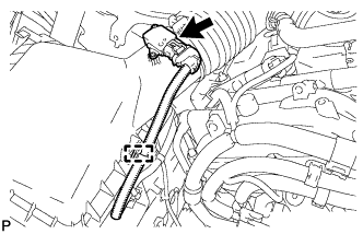
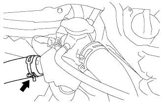
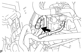
DISCONNECT UNION TO CHECK VALVE HOSE
-
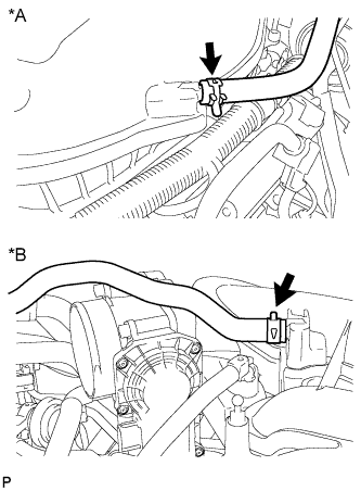
Text in Illustration *A for LHD *B for RHD Remove the clamp and disconnect the union to check valve hose.
-
-
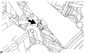
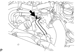
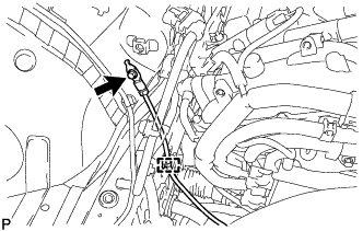
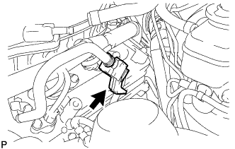
DISCONNECT PURGE LINE HOSE
-
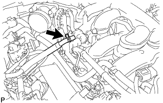
Remove the clamp and disconnect the purge line hose.
-
-
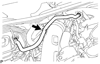
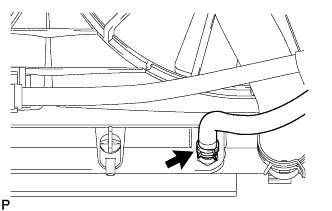
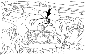
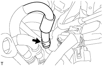
DISCONNECT NO. 1 RADIATOR HOSE
-
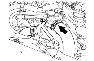
Remove the clamp and disconnect the No. 1 radiator hose.
-
-
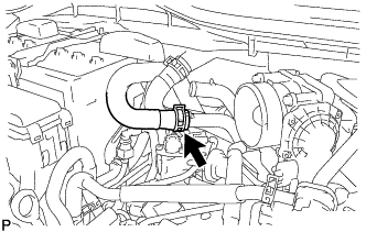
DISCONNECT NO. 2 RADIATOR HOSE
-
Disconnect the No. 2 radiator hose from the water inlet with thermostat sub-assembly.
-
-
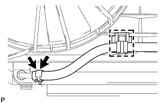
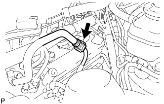
DISCONNECT RADIATOR RESERVOIR TANK HOSE
-
Remove the clamp and disconnect the radiator reservoir tank hose.
-
-
DISCONNECT NO. 2 OIL COOLER INLET HOSE (w/ Transmission Oil Cooler)
-
Disconnect the No. 2 oil cooler inlet hose from the radiator assembly.
-
-
DISCONNECT NO. 2 OIL COOLER OUTLET HOSE (w/ Transmission Oil Cooler)
-
Detach the flexible hose clamp and disconnect the No. 2 oil cooler outlet hose from the radiator assembly.
-
-
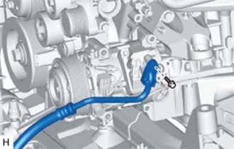
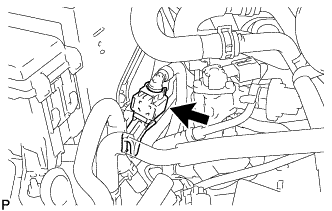
DISCONNECT INLET HEATER WATER HOSE
-
Disconnect the inlet heater water hose.
-
-
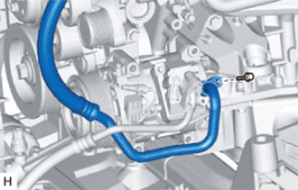
DISCONNECT OUTLET HEATER WATER HOSE
-
Disconnect the outlet heater water hose.
-
-
DISCONNECT NO. 1 COOLER REFRIGERANT DISCHARGE HOSE
-
Remove the bolt and disconnect the No. 1 cooler refrigerant discharge hose from the cooler compressor assembly.
-
Remove the O-ring from the No. 1 cooler refrigerant discharge hose.
Note
Seal the openings of the disconnected parts using vinyl tape to prevent moisture and foreign matter from entering them.
-
-
DISCONNECT SUCTION HOSE
-
Remove the bolt and disconnect the suction hose from the cooler compressor assembly.
-
Remove the O-ring from the suction hose.
Note
Seal the openings of the disconnected parts using vinyl tape to prevent moisture and foreign matter from entering them.
-
-
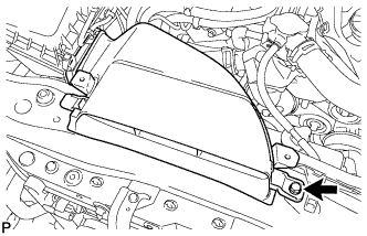
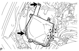
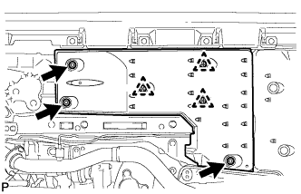
REMOVE ECM COVER
-
Remove the 3 bolts and ECM cover.
Note
-
Remove all water on and around the ECM cover.
-
Perform the inspection indoors to avoid rain.
-
Be sure to prevent water intrusion to the ECM (connectors and screw parts).
-
-
-
DISCONNECT ENGINE WIRE (for LHD)
-
Engine Room LH Side:
-
Disconnect the wire harness clamp and engine wire from the ECM box Click here.
-
-
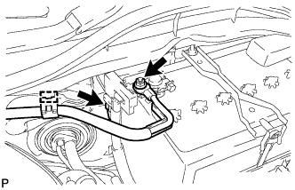
Engine Room RH Side:
-
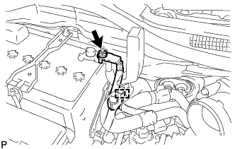
Remove the nut and disconnect the No. 2 engine wire and engine room main wire from the positive (+) battery terminal.
-
Disconnect the clamp.
-
Remove the No. 1 engine room relay block cover.
-
Remove the nut and disconnect the No. 4 engine wire from the No. 1 engine room junction block.
-
Disconnect the 2 wire harness clamps.
-
Remove the bolt, clamp and No. 3 engine wire.
-
-
-
DISCONNECT ENGINE WIRE (for RHD)
-
Engine Room LH Side:
-
Remove the nut and disconnect the No. 2 engine wire and engine room main wire from the positive (+) battery terminal.
-
Disconnect the clamp.
-
Remove the No. 1 engine room relay block cover.
-
Remove the nut and disconnect the No. 4 engine wire from the No. 1 engine room junction block.
-
Disconnect the wire harness clamp.
-
Disconnect the wire harness clamp and engine wire from the ECM box Click here.
-
-
Engine Room RH Side:
-
Remove the bolt, clamp and No. 3 engine wire.
-
-
-
DISCONNECT FUEL TUBE SUB-ASSEMBLY
-
Remove the fuel pipe clamp.
-
Disconnect the fuel tube sub-assembly from the fuel pipe Click here.
-
-
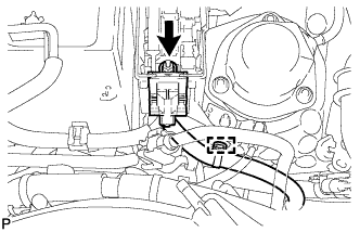
DISCONNECT NO. 2 FUEL HOSE
-
Remove the clamp and disconnect the No. 2 fuel hose.
-
-
DISCONNECT NO. 2 FUEL TUBE SUB-ASSEMBLY
-
Remove the fuel pipe clamp.
-
Disconnect the No. 2 fuel tube sub-assembly from the fuel pipe Click here.
-
-
REMOVE FRONT FLOOR COVER LH (for AWD)
-
Remove the 3 nuts, 3 grommets and front floor cover LH.
-
-
REMOVE NO. 1 REAR FLOOR BOARD SUB-ASSEMBLY
-
Remove the 4 grommets, 7 clips and No. 1 rear floor board sub-assembly.
-
-
REMOVE NO. 2 REAR FLOOR BOARD SUB-ASSEMBLY
-
Remove the 4 grommets, 7 clips and No. 2 rear floor board sub-assembly.
-
-
REMOVE FRONT CENTER FLOOR BRACE
-
Remove the 6 bolts, 2 nuts, 2 clips and front center floor brace.
-
-
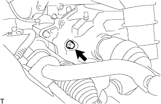
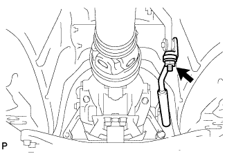
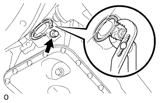
DISCONNECT HEATED OXYGEN SENSOR
-
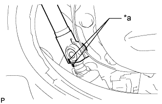
for Bank 1 Sensor 2:
-
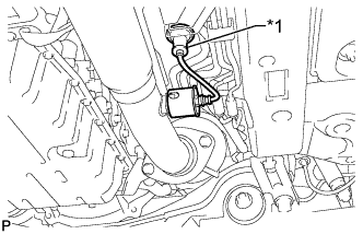
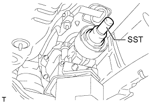
Text in Illustration *1 Grommet Disconnect the grommet of the heated oxygen sensor.
-
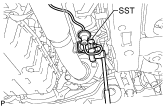
Using SST, disconnect the heated oxygen sensor.
- SST
- 09224-00010
-
-
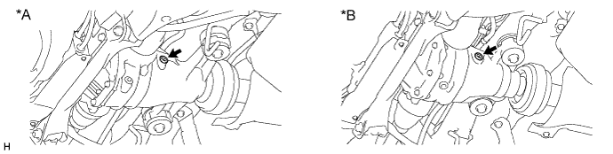
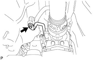
for Bank 2 Sensor 2:
-
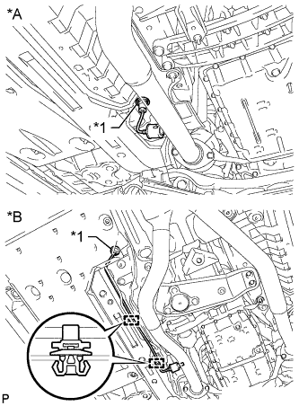
Text in Illustration *A for 2WD *B for AWD *1 Grommet for 2WD:
Disconnect the grommet of the heated oxygen sensor.
-
for AWD:
Disconnect the grommet and 2 clips of the heated oxygen sensor.
-
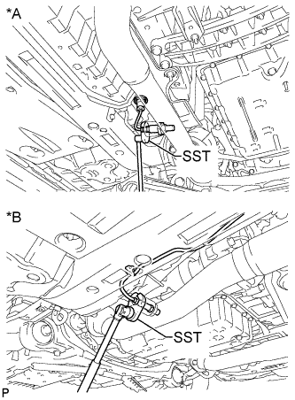
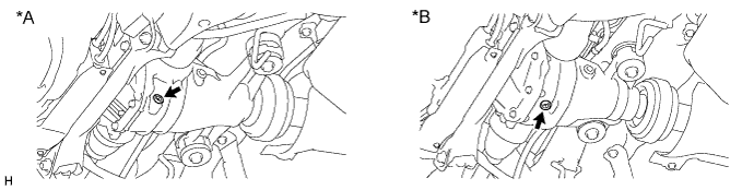
Text in Illustration *A for 2WD *B for AWD Using SST, disconnect the heated oxygen sensor.
- SST
- 09224-00010
-
-
-
REMOVE FRONT EXHAUST PIPE ASSEMBLY
-
Remove the 4 nuts, 8 bolts, 4 compression springs and front exhaust pipe assembly.
-
Remove the 4 gaskets.
-
w/ Protector:
Tech Tips
Only perform this procedure when replacement of the front No. 1 exhaust pipe protector is necessary.
-
Remove the bolt and clamp.
-
Remove the 2 bolts, 2 nuts, exhaust pipe protector stay and front No. 1 exhaust pipe protector.
-
-
-
REMOVE NO. 1 EXHAUST PIPE SUPPORT BRACKET SUB-ASSEMBLY
-
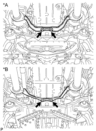
Text in Illustration *A for 2WD *B for AWD Remove the 2 bolts and No. 1 exhaust pipe support bracket.
-
-
REMOVE FRONT CENTER FLOOR BRACE SUB-ASSEMBLY (for 2WD)
-
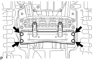
Remove the 4 bolts and front center floor brace sub-assembly.
-
-
REMOVE NO. 1 FUEL TANK PROTECTOR
-
Remove the 4 nuts and No. 1 fuel tank protector.
-
-
REMOVE FRONT NO. 1 FLOOR HEAT INSULATOR
-
Remove the 4 nuts and front No. 1 floor heat insulator.
-
-
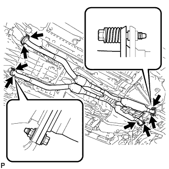
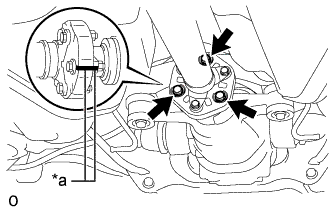
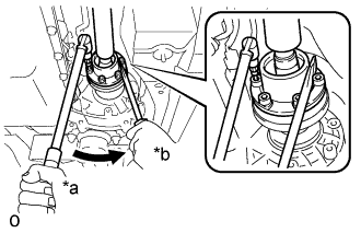
REMOVE PROPELLER WITH CENTER BEARING SHAFT ASSEMBLY (for 2WD)
-
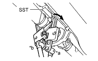
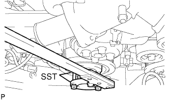
Text in Illustration *a Turn *b Hold Using SST, loosen the adjusting nut until it can be turned by hand.
- SST
- 09922-10010
Note
Make sure to turn SST in the direction shown in the illustration.
Tech Tips
Use 2 of the same type of SST.
-
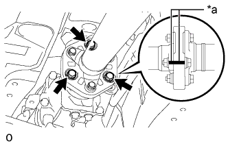
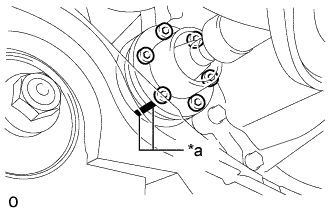
Text in Illustration *a Matchmark Put matchmarks on the transmission companion flange and flexible coupling.
-
Remove the 3 bolts, 3 washers and 3 nuts.
Note
The propeller intermediate shaft and flexible coupling should not be disconnected.
-
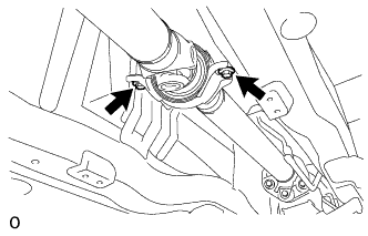
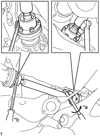
Text in Illustration *a Matchmark Put matchmarks on the differential companion flange and flexible coupling.
-
Remove the 3 bolts, 3 washers and 3 nuts.
Note
The propeller shaft assembly and flexible coupling should not be disconnected.
-
Remove the 2 bolts and 2 washers.
Tech Tips
Some vehicles are not equipped with the washers.
-
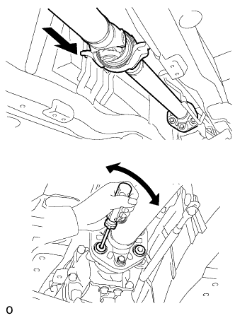
Push the propeller shaft assembly straight forward to compress the propeller shaft assembly and pull out the propeller shaft assembly from the centering pin of the differential.
Note
Press the propeller shaft assembly straight ahead to keep the transmission and propeller intermediate shaft aligned straight.
Tech Tips
If it is difficult to disconnect the flange from the flexible coupling, pry it using a screwdriver.
-
Pull the propeller shaft outward from the vehicle's rear.
Note
The propeller intermediate shaft and propeller shaft assembly should not be disconnected.
-
-
REMOVE PROPELLER WITH CENTER BEARING SHAFT ASSEMBLY (for AWD)
-
Text in Illustration *a Matchmark Put matchmarks on the differential companion flange and flexible coupling.
-
Remove the 3 bolts, 3 washers and 3 nuts.
Note
The propeller shaft assembly and flexible coupling should not be disconnected.
-
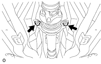
Remove the 2 bolts and 2 washers.
Tech Tips
Some vehicles are not equipped with the washers.
-
Pull out the propeller shaft.
-
Insert SST in the transmission to prevent oil leakage.
- SST
- 09325-40010
Note
Be careful not to damage the oil seal.
-
-
DISCONNECT STEERING SLIDING WITH SHAFT YOKE SUB-ASSEMBLY (for 2WD without VGRS)
-
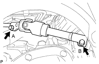
Loosen the bolt labeled A, remove the bolt labeled B.
Note
Do not remove the bolt labeled A, only loosen it.
-
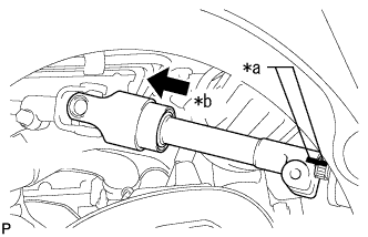
Text in Illustration *a Matchmarks *b Slide Slide the steering sliding with shaft yoke in the direction of the arrow and place matchmarks.
-
Disconnect the steering sliding with shaft yoke from the steering link.
-
-
DISCONNECT STEERING SLIDING WITH SHAFT YOKE SUB-ASSEMBLY (for 2WD with VGRS)
-
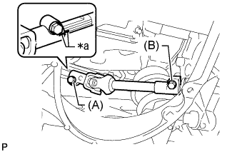
Text in Illustration *a Matchmark Loosen the bolt labeled A and remove the bolt labeled B, and then slide the steering sliding with shaft yoke sub-assembly.
Note
-
Do not remove the bolt labeled A.
-
Do not disconnect the steering sliding with shaft yoke sub-assembly from the power steering link assembly.
-
-
Put matchmark on the steering sliding with shaft yoke sub-assembly and steering actuator assembly.
-
Text in Illustration *a Matchmark Put matchmarks on the steering sliding with shaft yoke sub-assembly and power steering link assembly.
-
Disconnect the steering sliding with shaft yoke sub-assembly from the power steering link assembly.
-
Remove the bolt and steering sliding with shaft yoke sub-assembly from the steering actuator assembly.
-
-
DISCONNECT NO. 2 STEERING INTERMEDIATE SHAFT ASSEMBLY (for AWD)
-
Remove the bolt from the No. 2 steering intermediate shaft.
-

Text in Illustration *a Matchmarks *b Slide Slide the No. 2 steering intermediate shaft in the direction of the arrow and place matchmarks.
-
Disconnect the No. 2 steering intermediate shaft from the steering link.
-
-
DISCONNECT FRONT SPEED SENSOR LH (for AWD)
-
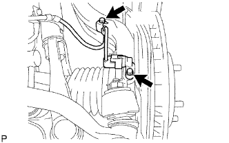
Remove the 2 bolts, and disconnect the speed sensor from the steering knuckle.
Note
-
Be careful not to damage the speed sensor.
-
Prevent foreign matter from adhering to the speed sensor.
-
-
-
DISCONNECT FRONT SPEED SENSOR RH (for AWD)
Tech Tips
Remove the RH side following the same procedure as for the LH side.
-
REMOVE FRONT AXLE SHAFT NUT LH (for AWD)
-
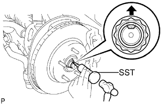
Using SST and a hammer, release the staked part of the front axle shaft nut.
- SST
- 09930-00010
Note
Release the staked part of the nut completely, otherwise the screw of the drive shaft may be damaged.
-
While applying the brakes, remove the front axle shaft nut.
-
-
REMOVE FRONT AXLE SHAFT NUT RH (for AWD)
Tech Tips
Remove the RH side following the same procedure as for the LH side.
-
DISCONNECT TIE ROD ASSEMBLY LH (for AWD)
-
Remove the clip and castle nut.
-
Install 2 spacers (SST spacer B) to the tie rod assembly LH so that there is a space of approximately 1 mm (0.0397 in.) between the arm and spacers.
- SST
- 09960-20010 ( 09961-02010 )
Note
-
Be sure to install the spacers (SST spacer B) as the steering knuckle spacer may shift.
-
As SST may become damaged, make sure the space between the arm and spacers is not 1 mm (0.0397 in.) or less.
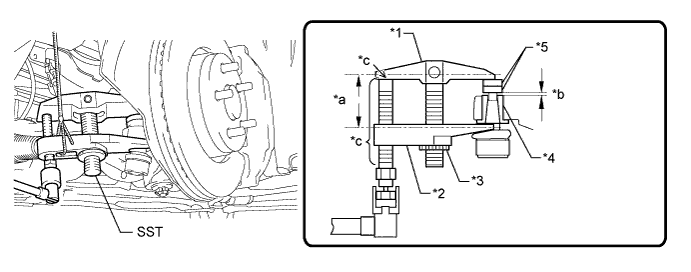
Text in Illustration *1 Body *2 Claw *3 Nut *4 Spacer *5 Spacer B - - *a Parallel *b 1 mm (0.0397 in.) *c Molybdenum Grease Application Area - - -
Using SST, disconnect the tie rod assembly from the steering knuckle.
- SST
- 09960-20010 ( 09961-02010 )
CAUTION:
Apply grease molybdenum grease to the bolt threads and the tip of SST.
Note
-
Do not damage the dust cover.
-
As the dust cover may be damaged, adjust SST with the center nut so that the body and claw are parallel.
-
Make sure to tie the string of SST to the vehicle to prevent SST from dropping.
-
If the axle carrier spacer (*4) comes out of position, replace the axle carrier.
-
-
DISCONNECT TIE ROD ASSEMBLY RH (for AWD)
Tech Tips
Remove the RH side following the same procedure as for the LH side.
-
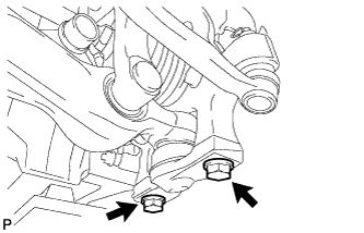
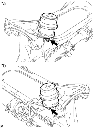
SEPARATE FRONT SHOCK ABSORBER ASSEMBLY LH (for 2WD)
-
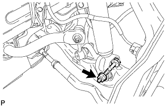
Loosen the bolt while holding the nut. Separate the lower part of the front shock absorber from the front suspension lower arm.
Note
Support the steering knuckle using a rubber attachment or other similar object to prevent excessive force from being applied to the flexible hose.
-
-
SEPARATE FRONT SHOCK ABSORBER ASSEMBLY RH (for 2WD)
Tech Tips
Remove the RH side following the same procedure as for the LH side.
-
SEPARATE FRONT SHOCK ABSORBER ASSEMBLY LH (for AWD)
-
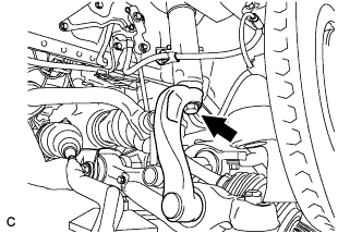
Remove the bolt. Then disconnect the absorber and absorber bracket.
Note
Support the steering knuckle using a rubber attachment or other similar object to prevent excessive force from being applied to the flexible hose.
-
-
SEPARATE FRONT SHOCK ABSORBER ASSEMBLY RH (for AWD)
Tech Tips
Remove the RH side following the same procedure as for the LH side.
-
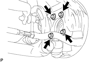
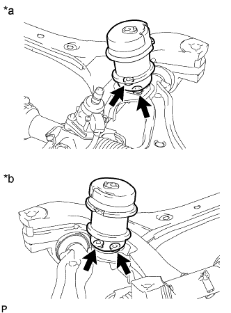
SEPARATE FRONT LOWER BALL JOINT ASSEMBLY LH (for 2WD)
-
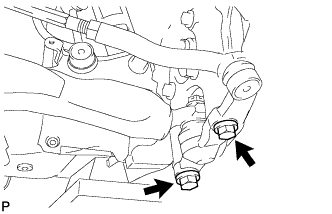
Remove the 2 bolts and steering knuckle from the lower ball joint.
-
-
SEPARATE FRONT LOWER BALL JOINT ASSEMBLY RH (for 2WD)
Tech Tips
Remove the RH side following the same procedure as for the LH side.
-
SEPARATE FRONT LOWER BALL JOINT ASSEMBLY LH (for AWD)
-
Remove the 2 bolts, and disconnect the front lower ball joint assembly.
-
-
SEPARATE FRONT LOWER BALL JOINT ASSEMBLY RH (for AWD)
Tech Tips
Remove the RH side following the same procedure as for the LH side.
-
DISCONNECT FRONT AXLE ASSEMBLY LH (for AWD)
-
Using a plastic-faced hammer, separate the front drive shaft assembly from the front axle hub.
Note
Be careful not to damage the drive shaft boot.
-
Remove the 4 bolts, front axle hub sub-assembly and front disc brake dust cover.
-
-
DISCONNECT FRONT AXLE ASSEMBLY RH (for AWD)
Tech Tips
Remove the RH side following the same procedure as for the LH side.
-
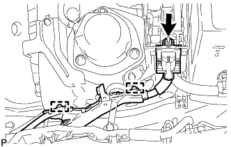
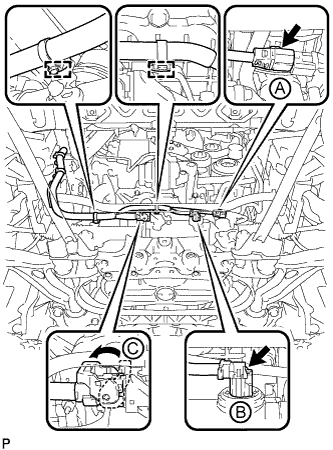
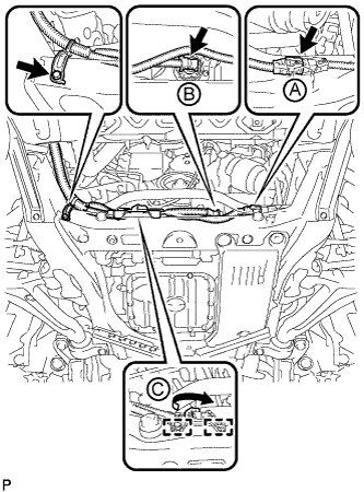
DISCONNECT POWER STEERING LINK WIRE HARNESS
-
for 2WD:
-
Disconnect the 2 wire harness clamps from the bracket.
-
Disconnect the 2 connectors (A) and (B) from the power steering link assembly.
-
Release the lock of connector (C) and disconnect the connector from the power steering link assembly.
-
-
for AWD:
-
Remove the bolt and disconnect the bracket from the front frame assembly.
-
Disconnect the 2 wire harness clamps from the front frame assembly.
-
Disconnect the 2 connectors (A) and (B) from the power steering link assembly.
-
Release the lock of connector (C) and disconnect the connector from the power steering link assembly.
-
-
-
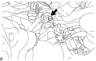
DISCONNECT FLOOR SHIFT GEAR SHIFTING ROD SUB-ASSEMBLY (for 2WD)
-
Remove the nut and disconnect the floor shift gear shifting rod sub-assembly.
-
-
DISCONNECT FLOOR SHIFT GEAR SHIFTING ROD SUB-ASSEMBLY (for AWD)
-
Remove the nut and disconnect the floor shift gear shifting rod sub-assembly.
-
-
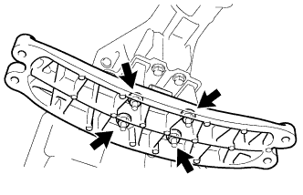
REMOVE FRONT NO. 2 UPPER SUSPENSION MEMBER (for 2WD)
-
Remove the 6 bolts and front No. 2 upper suspension member.
-
-
REMOVE NO. 1 FRAME CROSSMEMBER ASSEMBLY (for AWD)
-
Remove the 3 bolts and No. 1 frame crossmember assembly.
-
-
REMOVE NO. 2 FRAME CROSSMEMBER ASSEMBLY (for AWD)
-
Remove the 3 bolts and No. 2 frame crossmember assembly.
-
-
REMOVE FRONT LOWER SUSPENSION MEMBER PROTECTOR (for 2WD)
-
Remove the 4 bolts and suspension member protector.
-
-
REMOVE FRONT SUSPENSION MEMBER BRACE (for AWD)
-
Remove the 4 bolts and suspension member brace.
-
-
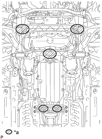
INSTALL ENGINE HANGER
-
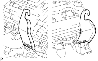
Install the 2 No. 1 engine hangers with the 4 bolts as shown in the illustration.
- Torque:
- 33 N*m { 337 kgf*cm, 24 ft.*lbf }
Tech Tips
No. 1 engine hanger 12281 - 31070 Bolt 91671 - F0822
-
-
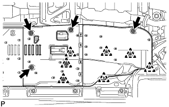
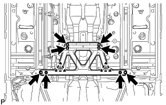
REMOVE ENGINE AND TRANSMISSION ASSEMBLY (for 2WD)
-
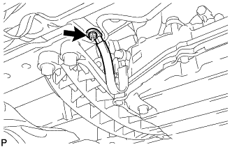
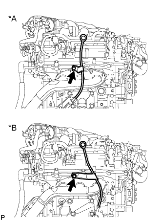
Remove the nut and disconnect the wire harness.
-
Text in Illustration *a Place Wooden Block or Plate Attachments Set the engine on an engine lifter.
Note
-
Place wooden blocks or plate lift attachments so that the engine is level.
-
With the exception of installing the engine assembly to an engine stand or removing the engine assembly from an engine stand, do not perform any work on the engine while it is suspended, as doing so is dangerous.
-
Never install attachments to the oil pan of the engine assembly or transmission as doing so may deform the oil pan.
-
-
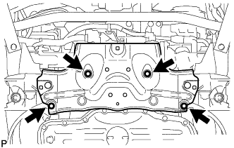
Remove the 4 bolts, and then separate the rear engine mounting member.
-
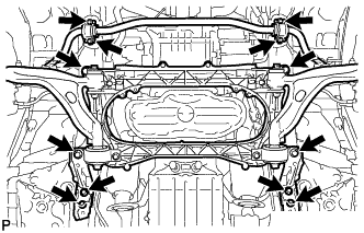
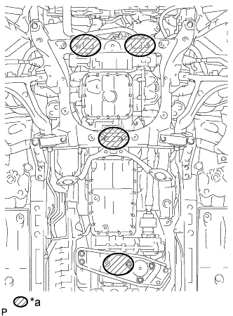
Remove the 10 bolts and 2 nuts shown in the illustration.
-
Operate the engine lifter, then slowly remove the engine from the vehicle.
Note
-
Make sure the engine is clear of all wiring and hoses.
-
While lowering the engine from the vehicle, do not allow it to contact the vehicle.
-
-
Attach an engine sling device and hang the engine with a chain block.
Note
Pay attention to the angle of the sling device as the engine assembly or engine hangers may be damaged or deformed if the angle is incorrect.
-
-
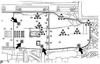
REMOVE ENGINE AND TRANSMISSION ASSEMBLY (for AWD)
-
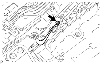
Remove the nut and disconnect the wire harness.
-
Text in Illustration *a Place Wooden Block or Plate Attachments Set the engine on an engine lifter.
Note
-
Place wooden blocks or plate lift attachments so that the engine is level.
-
With the exception of installing the engine assembly to an engine stand or removing the engine assembly from an engine stand, do not perform any work on the engine while it is suspended, as doing so is dangerous.
-
Never install attachments to the oil pan of the engine assembly or transmission as doing so may deform the oil pan.
-
-
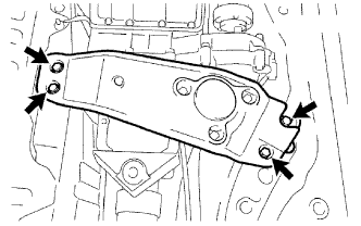
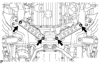
Remove the 4 bolts, then separate the rear engine mounting member.
-
Remove the 6 bolts and 2 nuts shown in the illustration.
-
Operate the engine lifter, then slowly remove the engine from the vehicle.
Note
-
Make sure the engine is clear of all wiring and hoses.
-
While lowering the engine from the vehicle, do not allow it to contact the vehicle.
-
-
Attach an engine sling device and hang the engine with a chain block.
Note
Pay attention to the angle of the sling device as the engine assembly or engine hangers may be damaged or deformed if the angle is incorrect.
-
-
REMOVE NO. 2 ENGINE OIL LEVEL DIPSTICK GUIDE
-
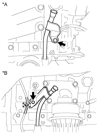
Text in Illustration *A for 2WD *B for AWD Remove the oil level dipstick.
-
Remove the bolt and No. 2 oil level dipstick guide.
-
Remove the O-ring from the No. 2 oil level dipstick guide.
-
-
REMOVE ENGINE OIL LEVEL DIPSTICK GUIDE
-
Text in Illustration *A for 2WD *B for AWD for AWD:
-
Remove the bolt and clamp, then remove the engine oil level dipstick guide.
-
-
Remove the bolt, then remove the engine oil level dipstick guide.
-
Remove the O-ring from the engine oil level dipstick guide.
-
-
REMOVE ENGINE UNDER COVER SUB-ASSEMBLY LH (for 2WD)
-
Remove the engine under cover sub-assembly LH.
-
-
REMOVE ENGINE UNDER COVER SUB-ASSEMBLY RH (for 2WD)
-
Remove the engine under cover sub-assembly RH.
-
-
REMOVE EXHAUST MANIFOLD SUB-ASSEMBLY LH
-
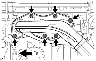
Text in Illustration *a Front Remove the 6 nuts, exhaust manifold sub-assembly LH and gasket.
-
-
REMOVE EXHAUST MANIFOLD SUB-ASSEMBLY RH
-
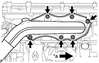
Text in Illustration *a Front Remove the 6 nuts, exhaust manifold sub-assembly RH and gasket.
-
-
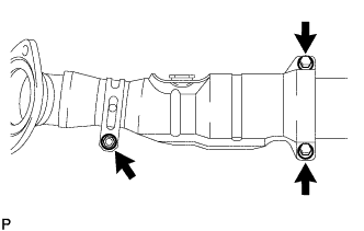
REMOVE FRONT PROPELLER SHAFT ASSEMBLY (for AWD)
-
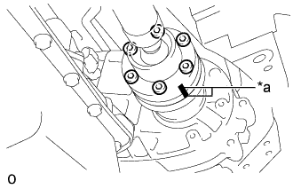
Text in Illustration *a Matchmark Put matchmarks on the transfer companion flange and the front propeller shaft assembly.
-
Text in Illustration *a Turn *b Hold Using a screwdriver or an equivalent, hold the transfer companion flange.
-
Using a socket hexagon wrench 6 mm, loosen the 6 bolts.
Note
-
Be careful not to damage the front propeller shaft.
-
To prevent the front propeller shaft from falling, only loosen the bolts. Do not remove them.
-
-
Text in Illustration *a Matchmark Put matchmarks on the front differential companion flange and the front propeller shaft assembly.
-
Text in Illustration *a Turn *b Hold Using a screwdriver or an equivalent, hold the transfer companion flange.
-
Using a socket hexagon wrench 6 mm, loosen the 6 bolts.
Note
-
Be careful not to damage the front propeller shaft.
-
To prevent the front propeller shaft from falling, only loosen the bolts. Do not remove them.
-
-
Remove the 12 bolts, 4 constant velocity universal joint washers and front propeller shaft assembly.
-
-
REMOVE STARTER ASSEMBLY
-
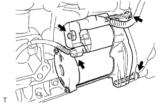
Disconnect the starter connector.
-
Detach the terminal cap.
-
Remove the nut and disconnect the starter cable.
-
Remove the 2 bolts and starter.
-
-
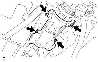
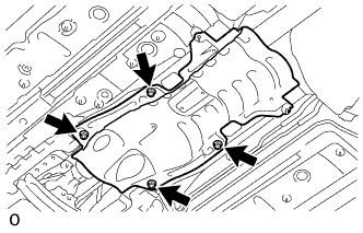
REMOVE FLYWHEEL HOUSING SIDE COVER
-
Remove the flywheel housing side cover from the engine assembly.
-
-
REMOVE DRIVE PLATE AND TORQUE CONVERTER CLUTCH SETTING BOLT
-
for 2WD Click here
-
for AWD Click here
-
-
REMOVE AUTOMATIC TRANSMISSION ASSEMBLY (for 2WD)
-
REMOVE AUTOMATIC WITH TRANSFER TRANSMISSION ASSEMBLY (for AWD)
-
REMOVE DRIVE PLATE AND RING GEAR SUB-ASSEMBLY
-
Using SST, hold the crankshaft pulley.
- SST
- 09213-70011 ( 09213-70020 )
- 09330-00021
-
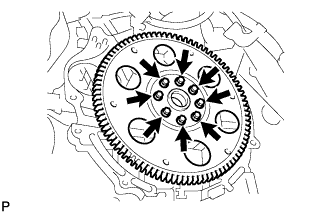
Remove the 8 bolts, front drive plate spacer, drive plate and rear drive plate spacer.
-
-
REMOVE FRONT DRIVE SHAFT ASSEMBLY LH (for AWD)
-
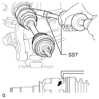
Using SST, remove the front drive shaft assembly LH.
- SST
- 09520-01010
- 09520-24010 ( 09520-32040 )
Note
-
Be careful not to damage the drive shaft boot, dust cover and oil seal.
-
Be careful not to drop the drive shaft assembly.
-
-
REMOVE FRONT DRIVE SHAFT ASSEMBLY RH (for AWD)
-
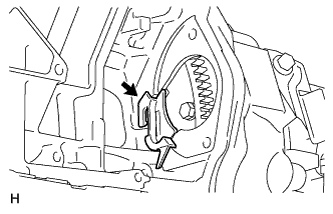
Using water pump pliers, remove the drive shaft bearing bracket hole snap ring.
-
Remove the No. 1 drive shaft bearing bracket setting bolt and front drive shaft assembly RH.
Note
-
Be careful not to damage the drive shaft boot and oil seal.
-
Be careful not to drop the drive shaft assembly.
-
-
-
REMOVE FRONT DIFFERENTIAL CARRIER ASSEMBLY (for AWD)
-
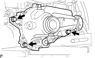
Support the front differential carrier assembly with a jack.
Note
Do not drop the front differential carrier assembly.
-
Remove the 3 bolts and front differential carrier assembly.
Note
-
Do not damage the installation surface when removing the front differential carrier assembly.
-
The remaining oil may leak out when removing the front differential carrier assembly.
-
Securely support the differential carrier while performing this step to avoid excessively tilting or dropping the differential carrier.
-
-
-
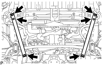
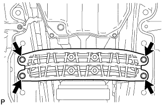
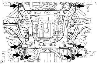
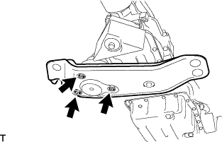
REMOVE FRONT SUSPENSION CROSSMEMBER SUB-ASSEMBLY (for 2WD)
-
Text in Illustration *a LH Side *b RH Side Remove the 2 bolts, then separate the front suspension crossmember sub-assembly from the engine.
-
-
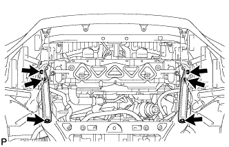
REMOVE FRONT FRAME ASSEMBLY (for AWD)
-
Text in Illustration *a LH Side *b RH Side Remove the 2 bolts, then separate the front frame assembly from the engine.
-
-
INSTALL ENGINE ON ENGINE STAND
-
Install the engine to an engine stand with bolts.
Note
-
Pay attention to the angle of the sling device as the engine assembly or engine hangers may be damaged or deformed if the angle is incorrect.
-
With the exception of installing the engine assembly to an engine stand or removing the engine assembly from an engine stand, do not perform any work on the engine while it is suspended, as doing so is dangerous.
-
-
Remove the 4 bolts and 2 engine hangers.
-
-
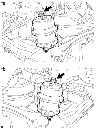
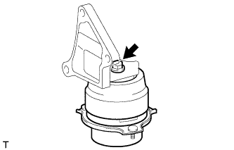
REMOVE FRONT ENGINE MOUNTING INSULATOR
Tech Tips
Only perform this procedure when replacement of the engine mounting insulator is necessary.
-
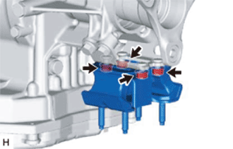
Text in Illustration *a LH Side *b RH Side for 2WD:
-
Remove the 2 nuts and front engine mounting insulator RH and LH.
-
-
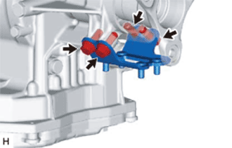
Text in Illustration *a LH Side *b RH Side for AWD:
-
Remove the 4 nuts and front engine mounting insulator RH and LH.
-
-
-
REMOVE REAR ENGINE MOUNTING MEMBER
-
for 2WD:
-
Remove the 4 nuts and rear engine mounting member from the rear engine mounting insulator.
-
-
for AWD:
-
Remove the 3 nuts and rear engine mounting member from the rear No. 1 engine mounting insulator.
-
-
-
REMOVE REAR ENGINE MOUNTING INSULATOR (for 2WD)
-
Remove the 4 bolts and rear engine mounting insulator from the rear engine mounting bracket.
-
-
REMOVE REAR ENGINE MOUNTING BRACKET (for 2WD)
-
Remove the 4 bolts and rear engine mounting bracket from the automatic transmission assembly.
-
-
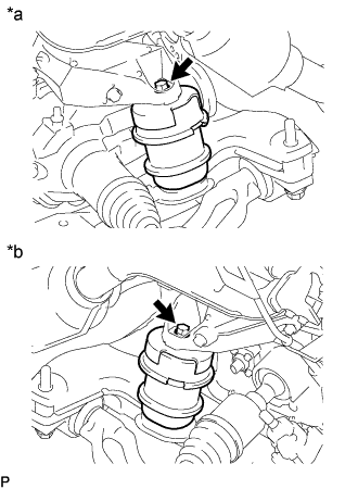
REMOVE REAR NO. 1 ENGINE MOUNTING INSULATOR (for AWD)
Tech Tips
Only perform this procedure when replacement of the engine mounting insulator is necessary.
-

Remove the 3 bolts and engine mounting bracket from the automatic transmission assembly.
-
Remove the bolt and rear No. 1 engine mounting insulator from the engine mounting bracket.
-