EXHAUST MANIFOLD INSTALLATION

-
INSTALL EXHAUST MANIFOLD SUB-ASSEMBLY LH
-
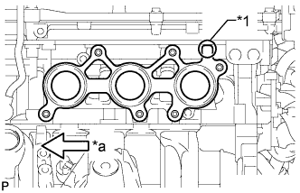
Text in Illustration *1 Protrusion *a Front Install a new gasket as shown in the illustration.
-
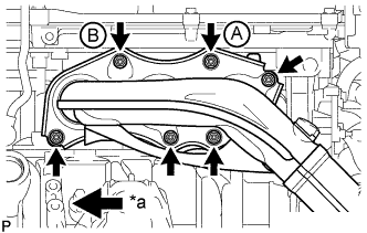
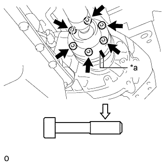
Text in Illustration *a Front Install the exhaust manifold sub-assembly LH with 6 new nuts.
- Torque:
- 21 N*m { 214 kgf*cm, 15 ft.*lbf }
Note
-
Do not damage the stud bolts when installing the exhaust manifold.
-
Be sure to tighten either the nut labeled A or B in the illustration first.
-
-
INSTALL EXHAUST MANIFOLD SUB-ASSEMBLY RH
-
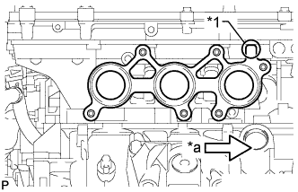
Text in Illustration *1 Protrusion *a Front Install a new gasket as shown in the illustration.
-
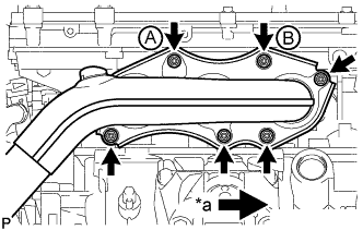
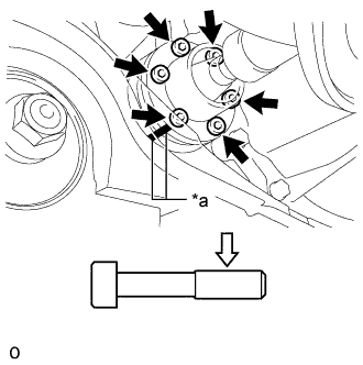
Text in Illustration *a Front Install the exhaust manifold sub-assembly RH with 6 new nuts.
- Torque:
- 21 N*m { 214 kgf*cm, 15 ft.*lbf }
Note
-
Do not damage the stud bolts when installing the exhaust manifold.
-
Be sure to tighten either the nut labeled A or B in the illustration first.
-
-
INSTALL NO. 2 ENGINE OIL LEVEL DIPSTICK GUIDE
-
Install a new O-ring to the No. 2 oil level dipstick guide.
-
Install the No. 2 oil level dipstick guide with the bolt.
- Torque:
- 21 N*m { 214 kgf*cm, 15 ft.*lbf }
-
Install the oil level dipstick.
-
-
INSTALL FRONT PROPELLER SHAFT ASSEMBLY (for AWD)
-
Completely remove any oil or the like and clean the constant velocity universal joint washers and the contact surfaces of the front propeller shaft assembly, transfer and front differential.
-
Align the matchmarks on the transfer companion flange and the front propeller shaft assembly.
-
Text in Illustration *a Matchmark 
Clean off oil and other foreign matter completely Temporarily tighten the front propeller shaft assembly with the 6 bolts and 2 constant velocity universal joint washers.
Note
Completely remove any oil or the like and clean the contact surfaces of the bolt.
-
Align the matchmarks on the differential companion flange and the front propeller shaft assembly.
-
Text in Illustration *a Matchmark Clean off oil and other foreign matter completely Temporarily tighten the front propeller shaft assembly with the 6 bolts and 2 constant velocity universal joint washers.
Note
Completely remove any oil or the like and clean the contact surfaces of the bolt.
-
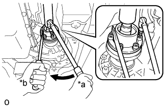
Text in Illustration *a Turn *b Hold Using a screwdriver or an equivalent, hold the transfer companion flange.
-
Using a socket hexagon wrench 6 mm, fully tighten the front propeller shaft assembly with the 6 bolts.
- Torque:
- 25 N*m { 255 kgf*cm, 18 ft.*lbf }
Note
Be careful not to damage the front propeller shaft.
-
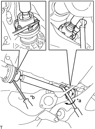
-
INSTALL NO. 1 EXHAUST PIPE SUPPORT BRACKET SUB-ASSEMBLY
-
Install the No. 1 exhaust pipe support bracket sub-assembly with the 2 bolts.
- Torque:
- 43 N*m { 438 kgf*cm, 32 ft.*lbf }
-
-
INSTALL FRONT EXHAUST PIPE ASSEMBLY
-
w/ Protector:
Tech Tips
Only perform this procedure when replacement of the front No. 1 exhaust pipe protector is necessary.
-
Install the front No. 1 exhaust pipe protector and exhaust pipe protector stay with the 2 bolts and 2 nuts.
- Torque:
- 11 N*m { 107 kgf*cm, 8 ft.*lbf }
-
Install the clamp with the bolt.
- Torque:
- 11 N*m { 107 kgf*cm, 8 ft.*lbf }
-
-
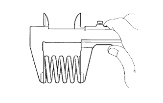
Using a vernier caliper, measure the free length of the compression springs.
Minimum free length 38.5 mm (1.52 in.) Tech Tips
If the free length is less than the minimum, replace the compression spring.
-
Install the 2 new gaskets to the front exhaust pipe assembly.
-
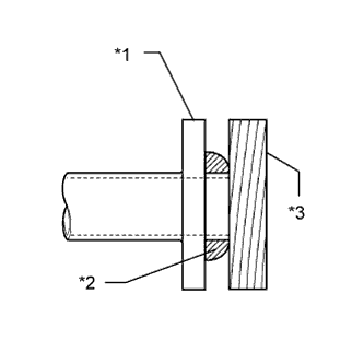
Text in Illustration *1 Front Exhaust Pipe Assembly *2 Gasket *3 Wooden Block Using a plastic-faced hammer and wooden block, tap in the new gasket until its surface is flush with the front exhaust pipe assembly.
Note
-
Be careful with the installation direction of the gasket.
-
Do not reuse the gasket.
-
Do not damage the gasket.
-
Do not push in the gasket by using the exhaust pipe when connecting it.
-
-
Install 2 new gaskets and the front exhaust pipe with 4 new nuts, 8 bolts and the 4 compression springs.
- Torque:
- for exhaust manifold side
- 39 N*m { 398 kgf*cm, 29 ft.*lbf }
- for tailpipe side
- 43 N*m { 438 kgf*cm, 32 ft.*lbf }
-
-
CONNECT HEATED OXYGEN SENSOR
-
for Bank 2 Sensor 2:
-
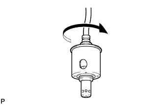
Before installing the heated oxygen sensor, twist the sensor wire counterclockwise 4 turns.
-
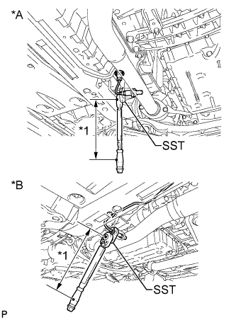
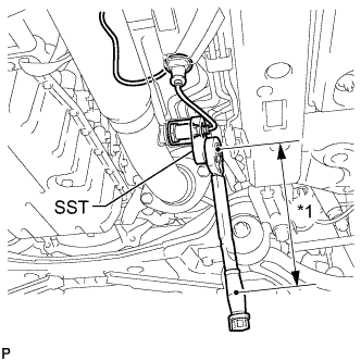
Text in Illustration *A for 2WD *B for AWD *1 Fulcrum Length Using SST, connect the heated oxygen sensor to the front exhaust pipe assembly.
- SST
- 09224-00010
- Torque:
- without SST
- 44 N*m { 449 kgf*cm, 32 ft.*lbf }
- with SST
- 40 N*m { 408 kgf*cm, 30 ft.*lbf }
Tech Tips
-
Use a torque wrench with a fulcrum length of 300 mm (11.8 in.). When using a torque wrench with a fulcrum length that is not 300 mm (11.8 in.), calculate the torque specification for the torque wrench and SST based on the "without SST" torque specification Click here.
-
Make sure SST and the wrench are connected in a straight line
-
After installing the sensor, check that the sensor wire is not twisted.
If the sensor wire is twisted, reinstall sensor.
-
for AWD:
Connect the grommet and attach the 2 clips of the heated oxygen sensor.
-
for 2WD:
Connect the grommet of the heated oxygen sensor.
-
-
for Bank 1 Sensor 2:
-
Before installing the heated oxygen sensor, twist the sensor wire counterclockwise 4 turns.
-
Text in Illustration *1 Fulcrum Length Using SST, connect the heated oxygen sensor to the front exhaust pipe assembly.
- SST
- 09224-00010
- Torque:
- without SST
- 44 N*m { 449 kgf*cm, 32 ft.*lbf }
- with SST
- 40 N*m { 408 kgf*cm, 30 ft.*lbf }
Tech Tips
-
Use a torque wrench with a fulcrum length of 300 mm (11.8 in.). When using a torque wrench with a fulcrum length that is not 300 mm (11.8 in.), calculate the torque specification for the torque wrench and SST based on the "without SST" torque specification Click here.
-
Make sure SST and the wrench are connected in a straight line.
-
After installing the sensor, check that the sensor wire is not twisted.
If the sensor wire is twisted, reinstall the sensor.
-
Connect the grommet of the heated oxygen sensor.
-
-
-
INSTALL FRONT CENTER FLOOR BRACE
-
Install the front center floor brace with the 2 clips, 6 bolts and 2 nuts.
- Torque:
- 19 N*m { 194 kgf*cm, 14 ft.*lbf }
-
-
INSTALL NO. 2 REAR FLOOR BOARD SUB-ASSEMBLY
-
Install the No. 2 rear floor board sub-assembly with the 4 grommets and 7 clips.
-
-
INSTALL NO. 1 REAR FLOOR BOARD SUB-ASSEMBLY
-
Install the No. 1 rear floor board sub-assembly with the 4 grommets and 7 clips.
-
-
INSTALL FRONT FLOOR COVER LH (for AWD)
-
Install the front floor cover LH with the 3 nuts and 3 grommets.
-
-
INSTALL NO. 2 ENGINE UNDER COVER (for 2WD)
-
Install the No. 2 engine under cover with the 4 screws and 2 grommets.
-
-
INSTALL FRONT SUSPENSION MEMBER BRACE (for 2WD)
-
Install the front suspension member brace with the clip and 4 bolts.
- Torque:
- 52 N*m { 530 kgf*cm, 38 ft.*lbf }
-
-
INSTALL AIR FUEL RATIO SENSOR
-
INSTALL GENERATOR ASSEMBLY (for AWD)
-
INSPECT FOR EXHAUST GAS LEAK
If gas is leaking, tighten the areas necessary to stop the leak. Replace damaged parts as necessary.