FUEL PUMP (for High Pressure) INSTALLATION

-
INSTALL NO. 2 FUEL PIPE SUB-ASSEMBLY
-
Install a new O-ring, new backup rings (No. 1, No. 2 and No. 3) and new E-ring to the No. 2 fuel pipe as shown in the illustration.
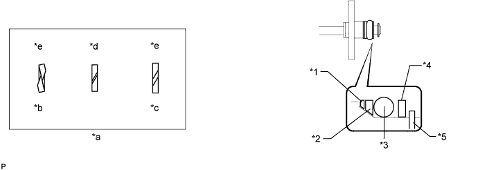
Text in Illustration *1 No. 1 Backup Ring *2 No. 2 Backup Ring *3 O-Ring *4 No. 3 Backup Ring *5 E-Ring - - *a Alignment Opening *b Overlapped *c Stretched *d CORRECT *e INCORRECT - - Note
-
Check that there is no foreign matter or damaged areas in the O-ring groove of the injector.
-
Check that the No. 1 and No. 2 backup rings are installed in the correct direction.
-
Make sure that the backup rings and O-ring are installed in the correct order.
-
Check that the alignment openings of the backup rings are not overlapped or stretched as shown in the illustration.
-
After installing the O-ring, check that it is not contaminated with foreign matter and is not damaged.
-
Check that the No. 3 fuel pipe installation end is not contaminated with foreign matter and is not damaged.
-
-
Apply gasoline to the O-ring and connect the fuel pipe to the delivery pipe.
Note
-
Do not install the No. 2 fuel pipe at an angle.
-
Do not install the bolt at this time.
-
-
-
INSTALL FUEL PUMP ASSEMBLY
-
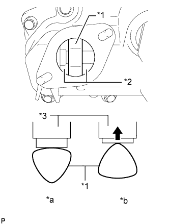
Text in Illustration *1 Camshaft *2 Oil Collector *3 Fuel Pump *a CORRECT *b INCORRECT Turn the crankshaft until the flat of the cam is facing the cylinder head cover's fuel pump attachment hole, as shown in the illustration.
Tech Tips
When installing the fuel pump by following the procedure described above: By not using the crankshaft pointed side to push up the pump activation surface, it is easier to install the fuel pump and No. 2 fuel pipe later.
-
Pour 30 cc of engine oil through the cylinder head cover's fuel pump attachment hole into the cylinder head oil collector.
-
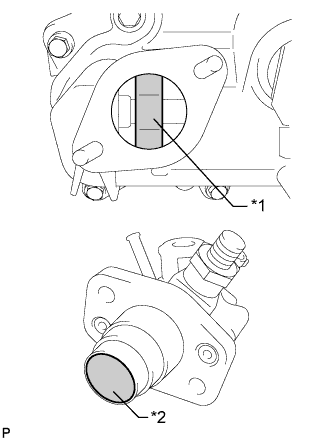
Text in Illustration *1 Camshaft *2 Pump Lifter Apply a coat of engine oil to the pump activation cam and pump lifter part.
-
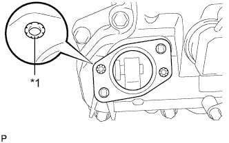
Text in Illustration *1 Metal Eyelets Install a new fuel pump insulator to the cylinder head cover. Then pass the 2 stud bolts through the holes of the fuel pump and insulator.
Note
Install the insulator so that the open sides of the metal eyelets are facing outward as shown in the illustration.
-
Temporarily install the No. 2 fuel pipe sub-assembly to the fuel pump assembly.
Note
Be careful not to damage the sealing surface of the fuel pipe when temporarily installing the fuel pipe.
-
Install the 2 nuts and tighten them in several passes.
- Torque:
- 25 N*m { 255 kgf*cm, 18 ft.*lbf }
-
-
CONNECT NO. 2 FUEL PIPE SUB-ASSEMBLY
-
Install the No. 2 fuel pipe to the delivery pipe with the 2 bolts.
- Torque:
- 10 N*m { 102 kgf*cm, 7 ft.*lbf }
-
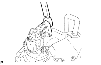
Using a 19 mm union nut wrench, connect the fuel pipe.
- Torque:
- 30 N*m { 306 kgf*cm, 22 ft.*lbf }
Tech Tips
The torque shown above should be used for tightening without using union nut wrench. When the union nut wrench is used for tightening, the torque should be calculated based on the length of the union nut wrench Click here.
-
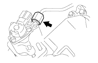
Connect the connector to the fuel pump.
-
-
INSTALL NO. 1 FUEL PIPE SUB-ASSEMBLY
-
Install the No. 1 fuel pipe sub-assembly with the 2 bolts.
- Torque:
- 10 N*m { 102 kgf*cm, 7 ft.*lbf }
-
Connect the 2 fuel hoses.
-
Connect the No. 2 fuel hose to the No. 1 fuel pipe sub-assembly.
-
-
INSTALL FUEL PRESSURE PULSATION DAMPER ASSEMBLY
-
Apply a light coat of engine oil to the threads and gasket seating surface of the fuel pressure pulsation damper assembly.
-
Install 2 new gaskets, the fuel tube and fuel pressure pulsation damper to the fuel pump.
-
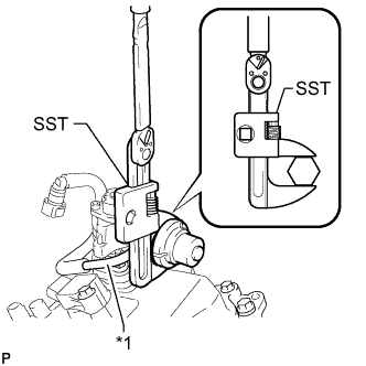
Text in Illustration *1 Fuel Tube Sub-assembly Using SST, tighten the fuel pressure pulsation damper to the fuel pump.
- SST
- 09922-10010
- Torque:
- without SST
- 40 N*m { 408 kgf*cm, 30 ft.*lbf }
- with SST
- 28 N*m { 281 kgf*cm, 20 ft.*lbf }
Tech Tips
-
The "with SST" torque value is effective when using a torque wrench with a fulcrum length of 300 mm (11.81 in.).
-
The torque shown above should be used for tightening without using SST. When SST is used for tightening, the torque should be calculated based on the length of SST Click here.
-
-
INSTALL NO. 3 WATER BY-PASS PIPE
-
Connect the 2 water by-pass hoses and install the No. 3 water by-pass pipe.
-
Install the bolt.
- Torque:
- 10 N*m { 102 kgf*cm, 7 ft.*lbf }
-
Attach the wire harness clamp to the No. 3 water by-pass pipe.
-
Connect the 2 heater water hoses.
-
-
INSTALL INTAKE MANIFOLD