FUEL PRESSURE SENSOR INSTALLATION

-
INSTALL FUEL PRESSURE SENSOR
-
Install a new gasket to the fuel pressure sensor.
-
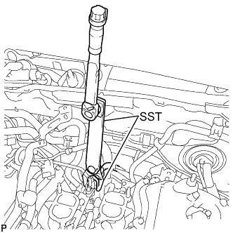
Using SST, install the fuel pressure sensor to the No. 1 delivery pipe.
- SST
- 09922-10240
- 09961-01270
- Torque:
- without SST
- 42 N*m { 428 kgf*cm, 31 ft.*lbf }
- with SST
- 23 N*m { 235 kgf*cm, 17 ft.*lbf }
Tech Tips
-
This torque value is effective when SST is parallel to the torque wrench.
-
This torque value can be obtained by using a torque wrench with a fulcrum length of 300 mm (11.8 in.) and SST with a fulcrum length of 240 mm (9.45 in.).
-
If using a torque wrench with a length that is not 300 mm (11.8 in.), calculate the torque specification for the torque wrench and SST based on the "without SST" torque specification Click here.
-
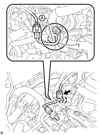
Text in Illustration *1 Wire Harness Connect the connector with the clamp.
Note
-
Make sure the wire harness of the fuel pressure sensor passes under the area labeled A as shown in the illustration.
-
Do not pull the wire harness of the fuel pressure sensor excessively.
-
-
-
INSTALL NO. 3 WATER BY-PASS PIPE
-
Connect the 2 water by-pass hoses and install the No. 3 water by-pass pipe.
-
Install the bolt.
- Torque:
- 10 N*m { 102 kgf*cm, 7 ft.*lbf }
-
Attach the wire harness clamp to the No. 3 water by-pass pipe.
-
Connect the 2 heater water hoses.
-
-
INSTALL FUEL RELIEF VALVE ASSEMBLY