ENGINE ASSEMBLY INSTALLATION

CAUTION:
As the engine assembly with transmission is extremely heavy, the engine lifter may suddenly drop if the instructions listed in the repair manual are not followed. Therefore, always follow the instructions listed in the repair manual when performing this procedure.
-
INSTALL REAR NO. 1 ENGINE MOUNTING INSULATOR
Tech Tips
Only perform this procedure when replacement of the engine mounting insulator is necessary.
-
Install the rear No. 1 engine mounting insulator to the automatic transmission assembly with the 4 bolts.
- Torque:
- 12 N*m { 117 kgf*cm, 8 ft.*lbf }
-
-
INSTALL FRONT ENGINE MOUNTING INSULATOR
Tech Tips
Only perform this procedure when replacement of the engine mounting insulator is necessary.
-
Install the front engine mounting insulator RH and LH with the 2 nuts.
- Torque:
- 70 N*m { 714 kgf*cm, 52 ft.*lbf }
-
-
INSTALL ENGINE HANGER
-
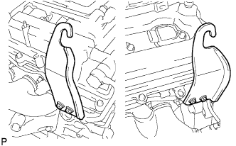
Install the 2 No. 1 engine hangers with the 4 bolts as shown in the illustration.
- Torque:
- 33 N*m { 337 kgf*cm, 24 ft.*lbf }
Tech Tips
No. 1 engine hanger 12281 - 31070 Bolt 91671 - F0822
-
-
REMOVE ENGINE STAND
-
Attach an engine sling device and hang the engine with a chain block.
Note
Pay attention to the angle of the sling device as the engine assembly or engine hangers may be damaged or deformed if the angle is incorrect.
-
Lift the engine and remove it from the engine stand.
Note
With the exception of installing the engine assembly to an engine stand or removing the engine assembly from an engine stand, do not perform any work on the engine while it is suspended, as doing so is dangerous.
-
Place the engine onto a work bench.
-
-
INSTALL FRONT SUSPENSION CROSSMEMBER SUB-ASSEMBLY
-
Install the front suspension crossmember sub-assembly with the 2 bolts.
- Torque:
- 35 N*m { 357 kgf*cm, 26 ft.*lbf }
-
-
INSTALL DRIVE PLATE AND RING GEAR SUB-ASSEMBLY
-
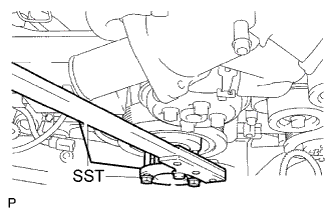
Using SST, hold the crankshaft pulley.
- SST
- 09213-70010 ( 09213-70020 )
- 09330-00021
-
Clean the 8 bolts and 8 bolt holes.
-
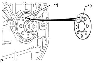
Text in Illustration *1 Pin Hole *2 Pin Install the front drive plate spacer.
Tech Tips
Align the pin of the front drive plate spacer with the pin hole of the crankshaft.
-
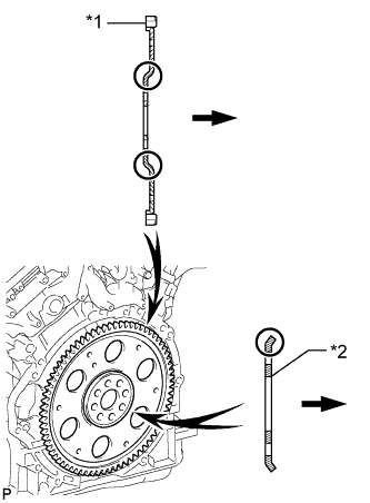
Text in Illustration *1 Drive Plate *2 Rear Drive Plate Spacer 
Transmission Install the drive plate and ring gear sub-assembly and rear drive plate spacer onto the crankshaft.
-
Apply a few drops of adhesive to 2 or 3 threads of the 6 bolt tips.
Adhesive Toyota Genuine Adhesive 1324, Three Bond 1324 or equivalent -
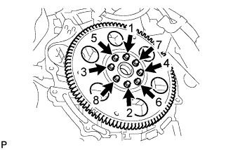
In several steps, uniformly install and tighten the 8 bolts in the sequence shown in the illustration.
- Torque:
- 83 N*m { 846 kgf*cm, 61 ft.*lbf }
-
-
INSTALL AUTOMATIC TRANSMISSION ASSEMBLY
-
INSTALL REAR ENGINE MOUNTING MEMBER
-
Install the engine rear mounting member to the automatic transmission assembly with the 4 nuts.
- Torque:
- 13 N*m { 133 kgf*cm, 10 ft.*lbf }
-
-
INSTALL DRIVE PLATE AND TORQUE CONVERTER CLUTCH SETTING BOLT
-
Using SST, hold the crankshaft pulley.
- SST
- 09213-70011 ( 09213-70020 )
- 09330-00021
-
Install the 6 drive plate and torque converter setting bolt.
- Torque:
- 41 N*m { 418 kgf*cm, 30 ft.*lbf }
Note
Install the black colored bolt first, and then the silver colored 5 bolts.
-
-
INSTALL FLYWHEEL HOUSING SIDE COVER
-
Install the flywheel housing side cover to the engine.
Note
Make sure that the flywheel housing side cover is securely installed.
-
-
INSTALL STARTER ASSEMBLY
-
Install the starter with the 2 bolts.
- Torque:
- 58 N*m { 591 kgf*cm, 43 ft.*lbf }
-
Connect the starter cable with the nut, and then attach the terminal cap.
- Torque:
- 9.8 N*m { 100 kgf*cm, 87 in.*lbf }
-
Connect the starter connector.
-
-
INSTALL EXHAUST MANIFOLD SUB-ASSEMBLY LH
-
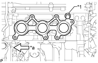
Text in Illustration *1 Protrusion *a Front Install a new gasket as shown in the illustration.
-
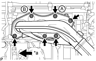
Text in Illustration *a Front Install the exhaust manifold sub-assembly LH with 6 new nuts.
- Torque:
- 21 N*m { 214 kgf*cm, 15 ft.*lbf }
Note
-
Do not damage the stud bolts when installing the exhaust manifold.
-
Be sure to tighten either the nut labeled A or B in the illustration first.
-
-
INSTALL EXHAUST MANIFOLD SUB-ASSEMBLY RH
-
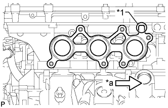
Text in Illustration *1 Protrusion *a Front Install a new gasket as shown in the illustration.
-
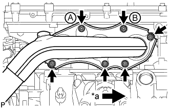
Text in Illustration *a Front Install the exhaust manifold sub-assembly RH with 6 new nuts.
- Torque:
- 21 N*m { 214 kgf*cm, 15 ft.*lbf }
Note
-
Do not damage the stud bolts when installing the exhaust manifold.
-
Be sure to tighten either the nut labeled A or B in the illustration first.
-
-
INSTALL ENGINE UNDER COVER SUB-ASSEMBLY LH
-
Install the engine under cover sub-assembly LH.
-
-
INSTALL ENGINE UNDER COVER SUB-ASSEMBLY RH
-
Install the engine under cover sub-assembly RH.
-
-
INSTALL ENGINE OIL LEVEL DIPSTICK GUIDE
-
Install a new O-ring to the engine oil level dipstick guide.
-
Apply a light coat of engine oil to the O-ring.
-
Push in the engine oil level dipstick guide end into the guide hole.
-
Install the engine oil level dipstick guide with the bolt.
- Torque:
- 10 N*m { 102 kgf*cm, 7 ft.*lbf }
-
Connect the clamp.
-
-
INSTALL NO. 2 ENGINE OIL LEVEL DIPSTICK GUIDE
-
Install a new O-ring to the No. 2 oil level dipstick guide.
-
Install the No. 2 oil level dipstick guide with the bolt.
- Torque:
- 21 N*m { 214 kgf*cm, 15 ft.*lbf }
-
Install the oil level dipstick.
-
-
INSTALL ENGINE AND TRANSMISSION ASSEMBLY
-
Set the engine on an engine lifter.
Note
-
Place wooden blocks or plate lift attachments so that the engine is level.
-
With the exception of installing the engine assembly to an engine stand or removing the engine assembly from an engine stand, do not perform any work on the engine while it is suspended, as doing so is dangerous.
-
Never install attachments to the oil pan of the engine assembly or transmission as doing so may deform the oil pan.
-
-
Remove the 4 bolts and 2 No. 1 engine hangers.
-
Operate the engine lifter and install the engine to the vehicle.
Note
Make sure that the engine is clear of all wiring and hoses.
-
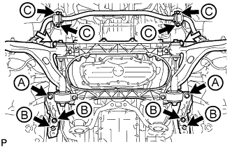
Install the engine and transmission assembly with crossmember with the 6 bolts, 4 new bolts and 2 nuts.
- Torque:
- for bolt A
- 194 N*m { 1978 kgf*cm, 143 ft.*lbf }
- for bolt B
- 50 N*m { 510 kgf*cm, 37 ft.*lbf }
- for bolt C
- 49 N*m { 500 kgf*cm, 36 ft.*lbf }
- for nut
- 151 N*m { 1540 kgf*cm, 111 ft.*lbf }
Text in Illustration Bolt 
Nut -
Install the rear engine mounting member with the 4 bolts.
- Torque:
- 35 N*m { 354 kgf*cm, 26 ft.*lbf }
-
Connect the wire harness with the nut.
- Torque:
- 5.4 N*m { 55 kgf*cm, 48 in.*lbf }
-
-
INSTALL FRONT LOWER SUSPENSION MEMBER PROTECTOR
-
Install the front lower suspension member protector with the 4 bolts.
- Torque:
- 5.5 N*m { 56 kgf*cm, 49 in.*lbf }
-
-
INSTALL FRONT NO. 2 UPPER SUSPENSION MEMBER
-
Install the 2 front No. 2 upper suspension members with the 6 bolts.
- Torque:
- 20 N*m { 204 kgf*cm, 15 ft.*lbf }
-
-
CONNECT FLOOR SHIFT GEAR SHIFTING ROD SUB-ASSEMBLY
-
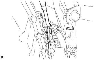
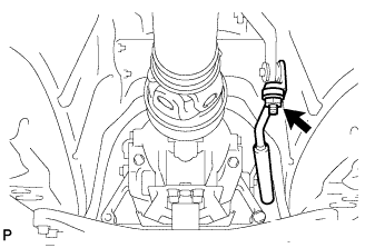
Connect the floor shift gear shifting rod sub-assembly to the transmission control shaft lever RH with the pin.
-
Install a new clip.
-
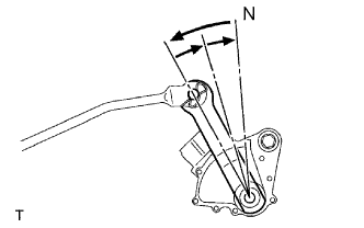
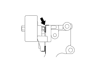
Turn the transmission control shaft lever RH of the park/neutral position switch assembly counterclockwise until it stops, and then turn it clockwise 2 notches to set it to the N position.
-
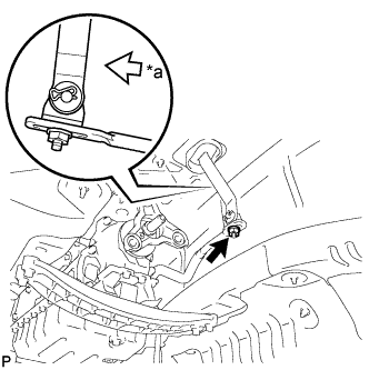
Temporarily install the floor shift gear shifting rod sub-assembly with the nut.
-
Tighten the nut while lightly pushing the lever rearward.
- Torque:
- 13 N*m { 130 kgf*cm, 9 ft.*lbf }
Text in Illustration *a Rear Note
Do not push the shift lever too hard.
-
-
CONNECT POWER STEERING LINK WIRE HARNESS
-
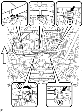
Connect the wire harness connector (C) to the power steering link assembly and securely lock the connector.
Text in Illustration Front -
Connect the 2 wire harness connectors (A) and (B) to the power steering link assembly.
-
Connect the 2 wire harness clamps to the bracket.
-
-
CONNECT FRONT LOWER BALL JOINT ASSEMBLY LH
-
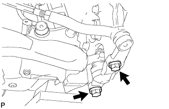
Install the steering knuckle to the lower ball joint with the 2 bolts.
- Torque:
- 150 N*m { 1530 kgf*cm, 111 ft.*lbf }
-
-
CONNECT FRONT LOWER BALL JOINT ASSEMBLY RH
Tech Tips
Install the RH side following the same procedure as for the LH side.
-
CONNECT FRONT SHOCK ABSORBER ASSEMBLY LH
-
Install the bolt on the lower side of the front shock absorber while holding the nut.
- Torque:
- 108 N*m { 1101 kgf*cm, 80 ft.*lbf }
-
-
CONNECT FRONT SHOCK ABSORBER ASSEMBLY RH
Tech Tips
Install the RH side following the same procedure as for the LH side.
-
CONNECT STEERING SLIDING WITH SHAFT YOKE SUB-ASSEMBLY
-
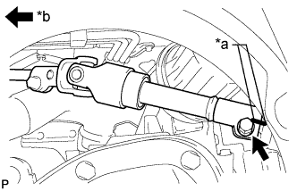
Text in Illustration *a Matchmark *b Vehicle Interior Align the matchmark on the steering sliding with shaft yoke with the matchmark on the power steering link and install the bolt.
- Torque:
- 35 N*m { 360 kgf*cm, 26 ft.*lbf }
-
Tighten the bolt closest to the vehicle interior.
- Torque:
- 35 N*m { 360 kgf*cm, 26 ft.*lbf }
-
-
INSTALL PROPELLER WITH CENTER BEARING SHAFT ASSEMBLY
-
Completely remove any oil or the like and clean the contact surfaces of the differential companion flange and propeller shaft companion flange.
-
Remove SST from the transmission.
-
Insert the yoke of the intermediate shaft into the transmission.
Note
Be careful not to damage the oil seal.
-
Align the matchmarks on the differential companion flange and propeller shaft companion flange.
-
Install and tighten the 4 bolts, 4 washers and 4 nuts.
- Torque:
- 74 N*m { 749 kgf*cm, 54 ft.*lbf }
Tech Tips
Install the washers on the same side as the bolts.
-
Temporarily install the 2 bolts with the 2 washers.
Tech Tips
Use the adjusting washers which were removed.
-
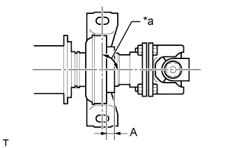
Text in Illustration *a 90° Adjust the distance (A) between the surface of the center support bearing and the surface of the cushion to 11.5 to 13.5 mm (0.453 to 0.531 in.) as shown in illustration.
Distance (A) 11.5 to 13.5 mm (0.453 to 0.531 in.) -
Tighten the 2 bolts.
- Torque:
- 49 N*m { 501 kgf*cm, 36 ft.*lbf }
-
-
INSPECT AND ADJUST NO. 2 AND NO. 3 JOINT ANGLE
Note
Measure the joint angle when the vehicle is raised using a four-post lift or when using a pit.
Tech Tips
If any vibration or noise occurs, perform the joint angle check as follows and replace the No. 2 center support bearing washer with a proper one.
-
Stabilize the propeller shaft and differential.
-
Turn the propeller shaft several times by hand to stabilize the center support bearing.
-
Using a jack, raise and lower the differential to stabilize the differential mounting cushion.
-
-
Check the No. 2 and No. 3 joint angles.
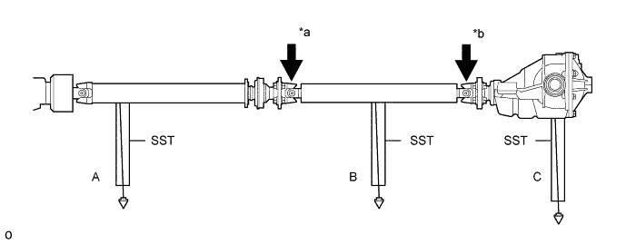
Text in Illustration *a No. 2 Joint Angle *b No. 3 Joint Angle
-
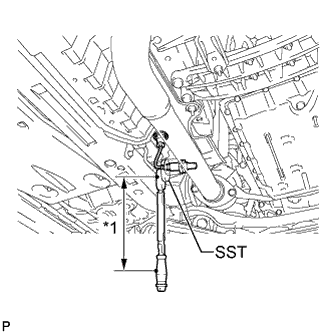
Using SST, measure the installation angle of the propeller intermediate shaft assembly and propeller shaft assembly.
- SST
- 09370-50010
Tech Tips
SST should be set directly underneath the shaft.
-
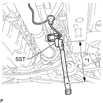
Using SST, measure the installation angle of the differential.
- SST
- 09370-50010
Tech Tips
Measure the installation angle by placing SST in the positions shown in the illustration.
-
Calculate the No. 2 joint angle.
No. 2 joint angle A - B = -1°10' to -0°10' A Propeller intermediate shaft installation angle B Propeller shaft assembly installation angle -
Calculate the No. 3 joint angle.
No. 3 joint angle B - C = 1°10' to 2°10' B Propeller shaft assembly installation angle C Differential installation angle If the measured angle is not within the specified range, adjust it with the center support bearing washers.
-
-
Adjust the No. 2 joint angle.
-
Select the center support bearing washers for adjustment.
Center Support Bearing Washer Part No. Thickness mm (in.) 90201-10106 2.0 (0.0787) 90201-10008 4.5 (0.1772) 90201-10033 6.5 (0.2559) 90201-10017 9.0 (0.3543) 90201-10034 11.0 (0.4331) Note
-
Make sure to use a washer of the same thickness on both the right and left sides.
-
Do not use 2 or more washers on a bolt.
-
-
-
-
INSTALL FRONT NO. 1 FLOOR HEAT INSULATOR
-
Install the front No. 1 floor heat insulator with the 4 nuts.
- Torque:
- 5.4 N*m { 55 kgf*cm, 48 in.*lbf }
-
-
INSTALL NO. 1 FUEL TANK PROTECTOR
-
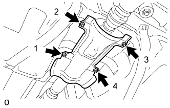
Install the No. 1 fuel tank protector with the 4 nuts and tighten the nuts in the order shown in the illustration.
- Torque:
- 5.0 N*m { 51 kgf*cm, 44 in.*lbf }
-
-
INSTALL FRONT CENTER FLOOR BRACE SUB-ASSEMBLY
-
Install the front center floor brace sub-assembly with the 4 bolts.
- Torque:
- 7.4 N*m { 75 kgf*cm, 65 in.*lbf }
-
-
INSTALL NO. 1 EXHAUST PIPE SUPPORT BRACKET SUB-ASSEMBLY
-
Install the No. 1 exhaust pipe support bracket sub-assembly with the 2 bolts.
- Torque:
- 43 N*m { 438 kgf*cm, 32 ft.*lbf }
-
-
INSTALL FRONT EXHAUST PIPE ASSEMBLY
-
w/ Protector:
Tech Tips
Only perform this procedure when replacement of the front No. 1 exhaust pipe protector is necessary.
-
Install the front No. 1 exhaust pipe protector and exhaust pipe protector stay with the 2 bolts and 2 nuts.
- Torque:
- 11 N*m { 107 kgf*cm, 8 ft.*lbf }
-
Install the clamp with the bolt.
- Torque:
- 11 N*m { 107 kgf*cm, 8 ft.*lbf }
-
-
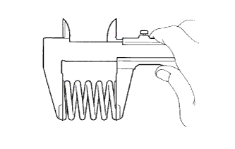
Using a vernier caliper, measure the free length of the compression springs.
Minimum free length 38.5 mm (1.52 in.) Tech Tips
If the free length is less than the minimum, replace the compression spring.
-
Install the 2 new gaskets to the front exhaust pipe assembly.
-
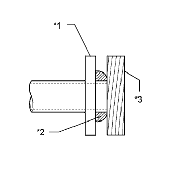
Text in Illustration *1 Front Exhaust Pipe Assembly *2 Gasket *3 Wooden Block Using a plastic-faced hammer and wooden block, tap in a new gasket until its surface is flush with the front exhaust pipe assembly.
Note
-
Be careful with the installation direction of the gasket.
-
Do not reuse the gasket.
-
Do not damage the gasket.
-
Do not push in the gasket by using the exhaust pipe when connecting it.
-
-
Install 2 new gaskets and the front exhaust pipe with 4 new nuts, 8 bolts and 4 compression springs.
- Torque:
- for exhaust manifold side
- 39 N*m { 398 kgf*cm, 29 ft.*lbf }
- for tailpipe side
- 43 N*m { 438 kgf*cm, 32 ft.*lbf }
-
-
CONNECT HEATED OXYGEN SENSOR
-
for Bank 2 Sensor 2:
-
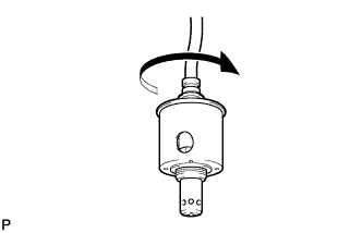
Before installing the heated oxygen sensor, twist the sensor wires counterclockwise 4 turns.
-
Text in Illustration *1 Fulcrum Length Using SST, connect the heated oxygen sensor to the front exhaust pipe assembly.
- SST
- 09224-00010
- Torque:
- without SST
- 44 N*m { 449 kgf*cm, 32 ft.*lbf }
- with SST
- 40 N*m { 408 kgf*cm, 30 ft.*lbf }
Tech Tips
-
Use a torque wrench with a fulcrum length of 300 mm (11.8 in.). When using a torque wrench with a fulcrum length that is not 300 mm (11.8 in.), calculate the torque specification for the torque wrench and SST based on the "without SST" torque specification Click here.
-
Make sure SST and the wrench are connected in a straight line.
-
After installing the sensor, check that the sensor wire is not twisted.
If the sensor wire is twisted, reinstall the sensor.
-
Connect the grommet of the heated oxygen sensor.
-
-
for Bank 1 Sensor 2:
-
Before installing the heated oxygen sensor, twist the sensor wires counterclockwise 4 turns.
-
Text in Illustration *1 Fulcrum Length Using SST, connect the heated oxygen sensor to the front exhaust pipe assembly.
- SST
- 09224-00010
- Torque:
- without SST
- 44 N*m { 449 kgf*cm, 32 ft.*lbf }
- with SST
- 40 N*m { 408 kgf*cm, 30 ft.*lbf }
Tech Tips
-
Use a torque wrench with a fulcrum length of 300 mm (11.8 in.). When using a torque wrench with a fulcrum length that is not 300 mm (11.8 in.), calculate the torque specification for the torque wrench and SST based on the "without SST" torque specification Click here.
-
Make sure SST and the wrench are connected in a straight line.
-
After installing the sensor, check that the sensor wire is not twisted.
If the sensor wire is twisted, reinstall the sensor.
-
Connect the grommet of the heated oxygen sensor.
-
-
-
INSTALL FRONT CENTER FLOOR BRACE
-
Install the front center floor brace with the 2 clips, 6 bolts and 2 nuts.
- Torque:
- 19 N*m { 194 kgf*cm, 14 ft.*lbf }
-
-
INSTALL NO. 2 REAR FLOOR BOARD SUB-ASSEMBLY
-
Install the No. 2 rear floor board sub-assembly with the 4 grommets and 7 clips.
-
-
INSTALL NO. 1 REAR FLOOR BOARD SUB-ASSEMBLY
-
Install the No. 1 rear floor board sub-assembly with the 4 grommets and 7 clips.
-
-
CONNECT FUEL TUBE SUB-ASSEMBLY
-
Connect the fuel tube sub-assembly Click here.
-
Install the fuel pipe clamp.
-
-
CONNECT NO. 2 FUEL HOSE
-
Connect the No. 2 fuel hose, and slide the clamp to secure the hose.
-
-
CONNECT FUEL TUBE SUB-ASSEMBLY
-
Connect the fuel tube sub-assembly Click here.
-
Install the fuel pipe clamp.
-
-
CONNECT ENGINE WIRE (for LHD)
-
Engine Room LH Side:
-
Connect the wire harness clamp and engine wire to the ECM box Click here.
-
-
Engine Room RH Side:
-
Install the bolt, clamp and No. 3 engine wire.
- Torque:
- 8.5 N*m { 87 kgf*cm, 75 in.*lbf }
-
Connect the 2 wire harness clamps.
-
Connect the No. 4 engine wire to the No. 1 engine room junction block with the nut.
- Torque:
- 11 N*m { 107 kgf*cm, 8 ft.*lbf }
-
Install the No. 1 engine room relay block cover.
-
Connect the clamp.
-
Connect the No. 2 engine wire and engine room main wire to the positive (+) battery terminal. Then, install it with the nut.
- Torque:
- 7.6 N*m { 77 kgf*cm, 67 in.*lbf }
-
-
-
CONNECT ENGINE WIRE (for RHD)
-
Engine Room LH Side:
-
Connect the wire harness clamp and engine wire to the ECM box Click here.
-
Connect the 2 wire harness clamps.
-
Connect the No. 4 engine wire to the No. 1 engine room junction block with the nut.
- Torque:
- 11 N*m { 107 kgf*cm, 8 ft.*lbf }
-
Install the No. 1 engine room relay block cover.
-
Connect the clamp.
-
Connect the No. 2 engine wire and engine room main wire to the positive (+) battery terminal. Then, install it with the nut.
- Torque:
- 7.6 N*m { 77 kgf*cm, 67 in.*lbf }
-
-
Engine Room RH Side:
-
Install the bolt, clamp and No. 3 engine wire.
- Torque:
- 8.5 N*m { 87 kgf*cm, 75 in.*lbf }
-
-
-
INSTALL ECM COVER
-
Install the ECM cover with the 3 bolts.
- Torque:
- 5.5 N*m { 56 kgf*cm, 49 in.*lbf }
Note
Make sure that the wire harness does not get caught between the parts.
-
-
CONNECT SUCTION HOSE
-
Remove the attached vinyl tape from the suction hose.
-
Apply sufficient compressor oil (ND-OIL 8) to a new O-ring and the fitting surface of the cooler compressor assembly.
Compressor oil ND-OIL 8 or equivalent -
Install the O-ring on the suction hose.
-
Install the suction hose on the cooler compressor assembly with the bolt.
- Torque:
- 9.8 N*m { 100 kgf*cm, 87 in.*lbf }
-
-
CONNECT NO. 1 COOLER REFRIGERANT DISCHARGE HOSE
-
Remove the attached vinyl tape from the No. 1 cooler refrigerant discharge hose.
-
Apply sufficient compressor oil (ND-OIL 8) to a new O-ring and the fitting surface of the cooler compressor assembly.
Compressor oil ND-OIL 8 or equivalent -
Install the O-ring on the No. 1 cooler refrigerant discharge hose.
-
Install the No. 1 cooler refrigerant discharge hose on the cooler compressor assembly with the bolt.
- Torque:
- 9.8 N*m { 100 kgf*cm, 87 in.*lbf }
-
-
CONNECT OUTLET HEATER WATER HOSE
-
Connect the outlet heater water hose, and slide the clamp to secure the hose.
-
-
CONNECT INLET HEATER WATER HOSE
-
Connect the inlet heater water hose, and slide the clamp to secure the hose.
-
-
CONNECT RADIATOR RESERVOIR TANK HOSE
-
Connect the radiator reservoir tank hose, and slide the clamp to secure the hose.
-
-
CONNECT NO. 2 RADIATOR HOSE
-
Connect the No. 2 radiator hose to the water inlet with thermostat sub-assembly and secure it with the clip.
-
-
CONNECT NO. 1 RADIATOR HOSE
-
Connect the No. 1 radiator hose, and slide the clamp to secure the hose.
-
-
CONNECT PURGE LINE HOSE
-
Connect the purge line hose to the purge VSV, and slide the clamp to secure the hose.
-
-
CONNECT UNION TO CHECK VALVE HOSE
-
Connect the union to check valve hose to the intake air surge tank, and slide the clip to secure the hose.
-
-
INSTALL AIR CLEANER CASE SUB-ASSEMBLY
-
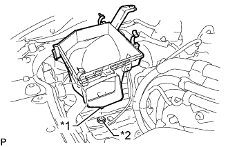
Text in Illustration *1 Pin *2 Grommet Insert the pin on the lower side of the air cleaner case into the grommet.
-
Install the air cleaner case, clamp and 2 bolts.
- Torque:
- 5.0 N*m { 51 kgf*cm, 44 in.*lbf }
Note
During removal, do not lose the grommet on the underside of the air cleaner case.
-
-
INSTALL AIR CLEANER FILTER ELEMENT SUB-ASSEMBLY
-
INSTALL AIR CLEANER CAP WITH AIR CLEANER HOSE
-
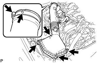
Install the air cleaner cap with air cleaner hose assembly with the 4 clamps and hose clamp.
- Torque:
- 4.0 N*m { 41 kgf*cm, 35 in.*lbf }
Tech Tips
Fit the protrusion on the air cleaner hose into the hole of the hose clamp on the throttle valve side.
-
for RHD:
Connect the union to check valve hose.
-
Connect the VSV hose to the air cleaner hose.
-
Connect the mass air flow meter connector and clamp to the air cleaner.
-
-
INSTALL NO. 1 AIR CLEANER INLET
-
Install the No. 1 air cleaner inlet with the bolt.
- Torque:
- 5.0 N*m { 51 kgf*cm, 44 in.*lbf }
-
-
ADD ENGINE OIL
-
Add clean engine oil.
Note
Do not allow engine oil to adhere to the moving parts of the belt tensioner, as this may cause malfunctions.
If engine oil is on the location indicated by the arrow, replace the belt tensioner.
Standard Oil Grade Oil Grade Oil Viscosity (SAE)
-
API grade SL "energy-conserving", SM "energy-conserving", SN "resource-conserving" or ILSAC multigrade engine oil
-
5W-30
-
10W-30
API grade SL, SM or SN multigrade engine oil
-
15W-40
-
20W-50
Standard Oil Grade (for Korea) Oil Grade Oil Viscosity (SAE)
-
API grade SL "energy-conserving", SM "energy-conserving", SN "resource-conserving" or ILSAC multigrade engine oil
-
0W-20
-
5W-20
-
5W-30
-
10W-30
API grade SL, SM or SN multigrade engine oil
-
15W-40
-
20W-50
Standard Capacity Item Specified Condition Drain and refill without oil filter change 5.9 liters (6.2 US. qts., 5.2 Imp. qts.) Drain and refill with oil filter change 6.3 liters (6.7 US. qts., 5.5 Imp. qts.) Dry fill 7.2 liters (7.6 US. qts., 6.3 Imp. qts.) -
-
Install the oil filler cap.
-
-
ADD AUTOMATIC TRANSMISSION FLUID
-
CONNECT CABLE TO NEGATIVE BATTERY TERMINAL
Note
When disconnecting the cable, some systems need to be initialized after the cable is reconnected Click here.
-
PERFORM INITIALIZATION
-
ADJUST SHIFT LEVER POSITION
-
While pushing the shift lock release button, move the shift lever to N.
-
Remove the nut and disconnect the floor shift gear shifting rod sub-assembly.
-
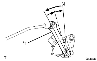
Text in Illustration *1 Transmission Control Shaft Lever RH Turn the transmission control shaft lever RH of the park/neutral position switch assembly counterclockwise until it stops, and turn it clockwise 2 notches to set it to the N position.
-

Temporarily install the floor shift gear shifting rod sub-assembly with the nut.
-
Tighten the nut while lightly pushing the lever rearward.
- Torque:
- 13 N*m { 130 kgf*cm, 9 ft.*lbf }
Text in Illustration *a Rear Note
Do not push the shift lever too hard.
-
-
INSPECT SHIFT LEVER POSITION
-
When moving the shift lever from P to R with the engine switch on (IG) and the brake pedal depressed, make sure that the shift lever moves smoothly and correctly into the position.
-
Start the engine and make sure that the vehicle moves forward when moving the shift lever from N to D and moves rearward when moving the shift lever to R.
If the operation cannot be done as specified, inspect the park/neutral position switch assembly and check the shift lever assembly installation condition.
-
-
ADD ENGINE COOLANT
-
Tighten the radiator drain cock plug by hand.
-
Tighten the 2 cylinder block drain cock plugs.
- Torque:
- 13 N*m { 130 kgf*cm, 9 ft.*lbf }
-
Add TOYOTA Super Long Life Coolant (SLLC) to the water outlet sub-assembly opening.
Standard Capacity Item Specified Condition for LHD 10.9 liters (11.5 US qts, 9.6 Imp. qts) for RHD 11.0 liters (11.6 US qts, 9.7 Imp. qts) Tech Tips
TOYOTA vehicles are filled with TOYOTA SLLC at the factory. In order to avoid damage to the engine cooling system and other technical problems, only use TOYOTA SLLC or similar high quality ethylene glycol based non-silicate, non-amine, non-nitrite, non-borate coolant with long-life hybrid organic acid technology (coolant with long-life hybrid organic acid technology is a combination of low phosphates and organic acids).
-
Slowly pour coolant into the radiator reservoir tank until it reaches the full line.
-
Press the No. 1 and No. 2 radiator hoses several times by hand, and then check the level of the coolant.
If the coolant level is low, add coolant.
-
Install the radiator cap.
-
Bleed air from the cooling system.
Note
Before starting the engine to warm up the engine, turn the A/C switch off.
-
Warm up the engine until the thermostat opens. While the thermostat is open, circulate the coolant for several minutes.
CAUTION:
When pressing the radiator hoses:
-
Wear protective gloves.
-
Be careful as the radiator hoses are hot.
-
Keep your hands away from the radiator fans.
Tech Tips
The thermostat open timing can be confirmed by pressing the No. 1 radiator hose by hand, and checking when the engine coolant starts to flow inside the hose.
-
-
Maintain the engine speed at 2000 to 2500 rpm.
-
Press the No. 1 and No. 2 radiator hoses several times by hand to bleed air.
CAUTION:
When pressing the radiator hoses:
-
Wear protective gloves.
-
Be careful as the radiator hoses are hot.
-
Keep your hands away from the radiator fans.
-
-
-
Stop the engine, and wait until the engine coolant cools down to ambient temperature.
CAUTION:
Do not remove the radiator cap while the engine and radiator are still hot. Pressurized, hot engine coolant and steam may be released and cause serious burns.
-
Check the coolant level in the radiator reservoir tank.
If the coolant level is low, add SLLC to the radiator reservoir tank full line.
-
-
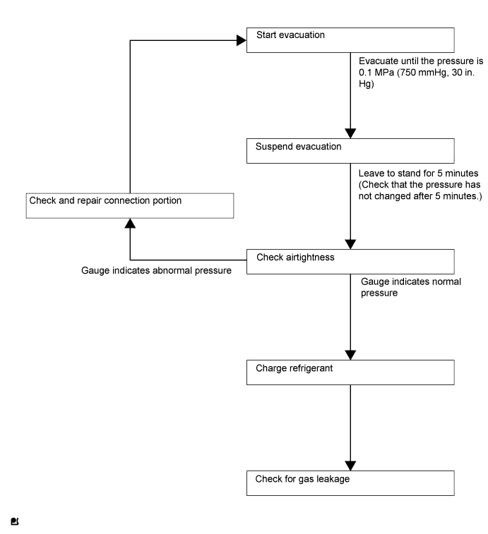
CHARGE REFRIGERANT
Tech Tips
Charge refrigerant in accordance with the equipment manual.
-
Perform vacuum purging using a vacuum pump.
-
Charge refrigerant HFC-134a (R134a).
- SST
- 09985-20010 ( 09985-02130, 09985-02150, 09985-02090, 09985-02110, 09985-02010, 09985-02050, 09985-02060, 09985-02070 )
Standard 500 +/-50 g (17.64 +/-1.76 oz) 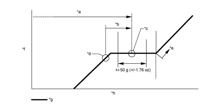
Text in Illustration *a Amount to be charged *b Charge 100 g (3.53 oz) *c Mean value in proper range *d Point where bubbles disappear *e Overcharged *f Pressure *g Sub-cool system *h Refrigerant amount Note
-
Do not operate the cooler compressor before charging refrigerant as the cooler compressor will not work properly without any refrigerant, and will overheat.
-
The system may need to be charged with approximately 100 g (3.53 oz) of refrigerant after bubbles disappear. The refrigerant amount should be checked by measuring its quantity, and not with the sight glass.
-
-
INSPECT FOR COOLANT LEAK
CAUTION:
Do not remove the radiator cap while the engine and radiator are still hot. Pressurized hot engine coolant and steam may be released and cause serious burns.
Note
Before performing each inspection, turn the A/C switch off.
-
Fill the radiator with coolant and attach a radiator cap tester.
-
Warm up the engine.
-
Using a radiator cap tester, increase the pressure inside the radiator to 137 kPa (1.4 kgf/cm2, 20 psi), and check that the pressure does not drop.
If the pressure drops, check the hoses, radiator and water pump for leaks. If no external leaks are found, check the heater core, cylinder block and cylinder head.
-
-
INSPECT FOR OIL LEAK
-
Start the engine. Make sure that no oil leaks from the connection point of the oil filter cap.
-
-
INSPECT FOR FUEL LEAK
-
Connect the GTS to the DLC3.
-
Turn the engine switch on (IG).
Note
Do not start the engine.
-
Turn the GTS on.
-
Enter the following menus: Powertrain / Engine and ECT / Active Test / Control the Fuel Pump / Speed.
-
-
Check the fuel pump operation.
-
Check for pressure in the fuel inlet tube from the fuel line. Check that sound of fuel flowing in the fuel tank can be heard.
If no sound can be heard, check the No. 1 integration relay, fuel pump, ECM and wiring connector.
-
-
Inspect for fuel leaks.
-
Check that there are no fuel leaks anywhere on the system after performing maintenance.
If there is a fuel leak, repair or replace parts as necessary.
-
-
-
INSPECT FOR EXHAUST GAS LEAK
If gas is leaking, tighten the areas necessary to stop the leak. Replace damaged parts as necessary.
-
INSPECT FOR REFRIGERANT LEAK
-
After recharging the refrigerant, check for refrigerant gas leakage using a halogen leak detector.
-
Perform the operation observing the following instructions:
-
Stop the engine.
-
Secure good ventilation (the halogen leak detector may react to volatile gases other than refrigerant, such as evaporated gasoline or exhaust gas).
-
Repeat the test 2 or 3 times.
-
Make sure that some refrigerant remains in the refrigeration system.
Tech Tips
When the compressor is off: approximately 392 to 588 kPa (4.0 to 6.0 kgf/cm2, 57 to 85 psi).
-
-
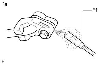
Text in Illustration *1 Halogen Leak Detector *a Check for Leakage Using a halogen leak detector, check the refrigerant line for leakage.
-
If a gas leak is not detected from the drain hose, remove the blower motor control (blower resistor) from the cooling unit. Insert the halogen leak detector sensor into the unit and check for gas leakage.
-
Disconnect the pressure switch connector and wait for approximately 20 minutes. Bring the halogen leak detector close to the pressure switch and check for gas leakage.
-
-
-
INSTALL FRONT WHEEL
- Torque:
- 103 N*m { 1050 kgf*cm, 76 ft.*lbf }
-
PLACE FRONT WHEELS FACING STRAIGHT AHEAD
-
CHECK AND ADJUST FRONT WHEEL ALIGNMENT
-
ADJUST MILLIMETER WAVE RADAR SENSOR ASSEMBLY (w/ Dynamic Radar Cruise Control System)
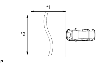
Text in Illustration *1 Approx. 10 m *2 Approx. 14 m Note
-
Perform measurements on a level surface.
-
Make sure that no large pieces of metal are within a 10 m (32.8 ft.) x 14 m (45.9 ft.) area in front of the vehicle. If possible, the surrounding area should also be free of large metal objects.
-
Before adjusting the radar beam axis, prepare the vehicle as follows.
-
Remove all excess weight from the vehicle (luggage, heavy objects, etc.).
-
Check the tire pressure and adjust it if necessary Click here.
-
-
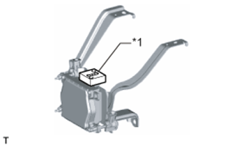
Text in Illustration *1 Level Check and adjust the vertical direction of the radar sensor.
-
Remove dust, oil and foreign matter from the radar sensor's level rack.
-
Set a level on the radar sensor's level rack.
-
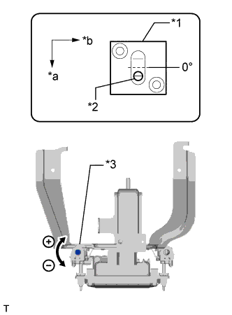
Text in Illustration *1 Level *2 Air Bubble *3 Bolt A *a FR *b LH Check that the level's air bubble is within the red frame.
OK Level's air bubble is within the red frame. If the bubble is not within the red frame, use a screwdriver to adjust bolt A until the air bubble is within the red frame.
Tech Tips
-
The adjustable range within the level's red frame is +/- 0.2°.
-
The target angle is +0.2° (upward angle of 0.2°).
Adjustment Adjustment Direction Adjustment Procedure Adjustment Angle Vertical adjustment Upward direction: Turn bolt A to negative (-) side For 1 complete turn of screwdriver, sensor moves about 0.12° Downward direction: Turn bolt A to positive (+) side
-
-
-
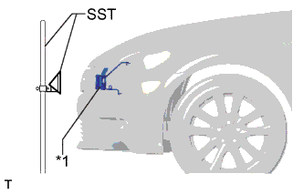
Text in Illustration *1 Millimeter Wave Radar Sensor Adjust the reflector height.
-
Adjust the reflector so that the center of SST reflector is the same height as the millimeter wave radar sensor.
- SST
- 09870-60000 ( 09870-60010 )
- 09870-60040
Tech Tips
Prepare a 10 m (32.8 ft.) string, a string with a sharp-pointed weight (plumb bob), and a 5 m (16.4 ft.) tape measure.
-
-
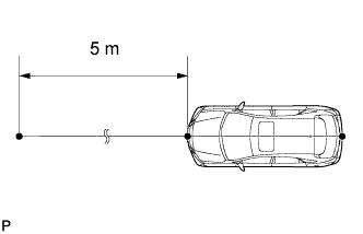
Place the reflector.
-
Hang the string (with weight) from the center of the vehicle's rear emblem. Mark the vehicle's rear center point on the ground. Repeat for the front of the vehicle.
-
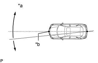
Text in Illustration *a Adjust Center By Moving String To Right And Left *b Extend String Through Front Center Mark Set one end of the 10 m (32.8 ft.) string on the vehicle's rear center point. Run the string over the vehicle's front center point to a position 5 m (16.4 ft.) beyond the vehicle's front center point as shown in the illustration. Mark the 5 m (16.4 ft.) position.
-
Place the reflector (SST) at the marked position.
Note
Perform the operation as precisely as possible.
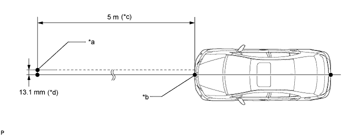
Text in Illustration *a Reflector (SST) Placement Point *b Millimeter Wave Radar Sensor Position *c 16.4 ft. *d 0.516 in.
-
-
Check the radar beam axis.
-
When using the GTS:
-
Connect the GTS to the DLC3.
-
Turn the engine switch on (IG).
-
Turn the GTS on, and turn the cruise control main switch on.
-
Select "Connect to Vehicle".
-
Select each item on the display screen and proceed to the next screen.
-
Under "System Selection Menu", select "Radar Cruise".
-
Select "Utility".
-
Select "Beam Axis Adjustment" and proceed to the next screen.
Tech Tips
A buzzer will sound for 1 second.
-
Follow the GTS display, and continue with the adjustment.
Note
-
Turn the cruise control main switch on before pressing "Next".
-
Make sure there is at least 20 cm (7.87 in.) between the radar sensor and any nearby individuals.
-
-
-
Check the following items on the radar cruise divergence data screen.
Note
While using the GTS beam axis adjustment mode, the actual direction and angle of the radar sensor may be different from the GTS data. In such a case, the deviation is displayed on the multi-information display in the combination meter.
-
Confirm that the distance value is approximately 5 m (16.4 ft.).
Tech Tips
-
A value between 0.0 m (0.0 ft.) and 6.3 m (20.7 ft.) should be indicated.
-
If the distance is 0.0 m (0.0 ft.), the sensor cannot detect the target. Reconfirm that there is no metal in the specified area in front of the vehicle (refer to the Notice at the beginning of this adjustment procedure).
-
-
Confirm that the left/right side value is between 0.0 m (0.0 ft.) and 6.3 m (20.7 ft.).
Tech Tips
If the distance is 0.0 m (0.0 ft.), the sensor cannot detect the target. Reconfirm that there is no metal in the specified area in front of the vehicle (refer to the Notice at the beginning of this adjustment procedure).
-
-
-
Check and adjust the horizontal direction of the radar sensor.
-
Check that the divergence of the radar beam axis is 0°.
Standard 0° (Both right and left) If the axis is not as specified, use a screwdriver to adjust bolt B until the divergence of the radar beam axis is 0°.
-
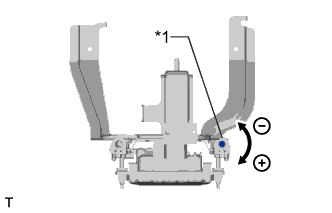
Text in Illustration *1 Bolt B Based on the measured divergence of the beam axis, turn and adjust bolt B for horizontal adjustment of the millimeter wave radar sensor using a screwdriver.
Adjustment Adjustment Direction Adjustment Procedure Adjustment Angle Horizontal adjustment Right direction: Turn bolt B to positive (+) side. For 1 complete turn of screwdriver, sensor moves about 0.07° Left direction: Turn bolt B to negative (-) side. Tech Tips
If the value does not change to 0°, it is possible that the sensor is aiming at something different. Reconfirm that there are no reflective materials in the surrounding area.
-
Select "Next". The driving learning value is automatically reset.
Tech Tips
A buzzer will sound for 10 seconds or more.
-
Disconnect the GTS from the DLC3.
-
-
Recheck and readjust the vertical direction of the radar sensor.
-
Text in Illustration *1 Level Set a level on the radar sensor's level rack.
-
Text in Illustration *1 Level *2 Air Bubble *3 Bolt A *a FR *b LH Check that the level's air bubble is within the red frame.
OK Level's air bubble is within the red frame. If the bubble is not within the red frame, use a screwdriver to adjust bolt A until the level's air bubble is within the red frame.
Tech Tips
-
The adjustable range within the red frame is +/- 0.2°.
-
The target angle is + 0.2° (upward angle of 0.2°).
Adjustment Adjustment Direction Adjustment Procedure Adjustment Angle Vertical adjustment Upward direction: Turn bolt A to negative (-) side For 1 complete turn of screwdriver, sensor moves about 0.12° Downward direction: Turn bolt A to positive (+) side
-
-
-
-
INSPECT THROTTLE WITH MOTOR BODY ASSEMBLY
Note
Perform the following procedure after replacing the ECM, throttle body assembly or any throttle body components. The following procedure should also be performed if the throttle body is cleaned.
-
Disconnect the cable from the negative (-) battery terminal. Wait at least 60 seconds and reconnect the cable.
Note
After the engine switch is turned off, the display and navigation module display (HDD navigation system) records various types of memory and settings. As a result, after turning the engine switch off, make sure to wait at least 60 seconds before disconnecting the cable from the negative (-) battery terminal.
-
Turn the engine switch on (IG) without operating the accelerator pedal.
Note
If the accelerator pedal is operated, perform the above steps again.
-
Connect the GTS to the DLC3 and clear the DTCs Click here.
-
Start the engine and check that the MIL is not illuminated. After the engine is warmed up, check that the idle speed is within the specified range when the A/C is switched off.
Standard Condition Engine Idle Speed A/C switched off 600 to 700 rpm Note
-
Be sure to perform this step with all accessories off.
-
Make sure that the shift lever is in neutral.
-
-
Enter the following menus: Powertrain / Engine and ECT / Data List / All Data / Throttle Sensor Position. Sensor Output. Fully depress the accelerator pedal and check that the value is 60% or more.
-
Perform a road test and confirm that there are no abnormalities.
-
-
INSPECT IGNITION TIMING
-
Warm up the engine and stop the engine.
Note
A warmed up engine should have an engine coolant temperature of over 80°C (176°F), and an engine oil temperature of 60°C (140°F), and the engine speed should be stabilized.
-
When using the GTS:
-
Connect the GTS to the DLC3.
-
Start the engine and idle it.
-
Turn the GTS on.
-
Enter the following menus: Powertrain / Engine and ECT / Data List / IGN Advance.
Standard ignition timing 7 to 17° BTDC at idle Note
When checking the ignition timing, the transmission should be in neutral.
Tech Tips
Refer to the GTS operator's manual for further details.
-
Check that the ignition timing advances immediately when the engine speed is increased.
-
Enter the following menus: Powertrain / Engine / Active Test / Connect the TC and TE1.
-
Monitor IGN Advance.
-
Perform the Active Test.
Standard ignition timing 8 to 12° BTDC at idle Note
When checking the ignition timing, the transmission should be in neutral or park.
Tech Tips
Refer to the GTS operator's manual for further details.
-
-
When not using the GTS:
-
Remove the V-bank cover sub-assembly.
-
Connect the tester probe of a timing light to the wire of the ignition connector for No. 1 cylinder.
Note
Use a timing light which can detect the primary signal.
-
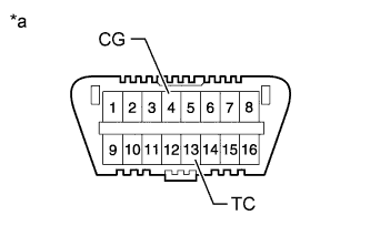
Text in Illustration *a Front view of DLC3 Using SST, connect terminals 13 (TC) and 4 (CG) of the DLC3.
- SST
- 09843-18040
Note
-
Confirm the terminal numbers before connecting them. Connecting the wrong terminals can damage the engine.
-
When checking the ignition timing, the transmission should be in neutral.
-
Using a timing light, check the ignition timing.
Standard ignition timing 8 to 12° BTDC at idle -
Remove SST from the DLC3.
-
Check the ignition timing.
Standard ignition timing 7 to 17° BTDC at idle -
Check that the ignition timing advances immediately when the engine speed is increased.
-
Disconnect the timing light from the engine.
-
Install the V-bank cover sub-assembly.
-
-
-
INSPECT ENGINE IDLE SPEED
-
Warm up and stop the engine.
Note
A warmed up engine should have an engine coolant temperature of over 80°C (176°F) and an engine oil temperature of 60°C (140°F), and the engine speed should be stabilized.
-
When using the GTS:
-
Connect the GTS to the DLC3.
Note
Switch off all accessories and A/C before connecting the GTS.
-
Race the engine at 2500 rpm for approx. 90 seconds.
-
Turn the GTS on.
-
Enter the following menus: powertrain / Engine and ECT / Data list / Engine Speed.
Standard idle speed 650 to 750 rpm Note
When checking the idle speed, the transmission should be in neutral.
Tech Tips
Refer to the GTS operator's manual for further details.
If the idle speed is not as specified, check the air intake system.
-
Disconnect the GTS from the DLC3.
-
-
When not using the GTS:
-
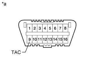
Text in Illustration *a Front view of DLC3 Using SST, connect the tachometer probe to terminal 9 (TAC) of the DLC3.
- SST
- 09843-18040
Note
Confirm the terminal numbers before connecting them. Connecting the wrong terminals can damage the engine.
-
Race the engine at 2500 rpm for approx. 90 seconds.
-
Check the idle speed.
Standard idle speed (Transmission neutral position) 650 to 750 rpm Note
When checking the idle speed, the transmission should be in neutral.
If the speed is not as specified, check the air intake system.
-
Disconnect the tachometer from the DLC3.
-
-
-
INSPECT CO/HC
Tech Tips
This is a check for determining whether or not the idle CO / HC complies with regulations.
-
Start the engine.
-
Keep the engine speed at 2500 rpm for approx. 180 seconds.
-
Insert the CO / HC meter testing probe at least 40 cm (1.31 ft.) into the tailpipe during idling.
-
Immediately check CO / HC concentration at idle and/or 2500 rpm.
Tech Tips
-
When performing the 2 mode (2500 rpm and idle) test, follow the measurement order prescribed by the applicable local regulations.
-
If the CO / HC concentration does not comply with regulations, troubleshoot in the order given below.
-
Check the DTCs Click here.
-
See the table below for possible causes, then inspect and correct the applicable causes if necessary.
CO HC Symptom Causes Normal High Rough idle
-
1. Faulty ignitions
-
Incorrect timing
-
Fouled, shorted or improperly gapped plugs
-
2. Leaky intake and exhaust valves
-
3. Leaky cylinder
Low High Rough idle
(Fluctuating HC reading)
-
1. Vacuum leaks
-
PCV hose
-
Intake manifold
-
Throttle body
-
2. Lean mixture causing misfire
High High Rough idle
(Black smoke from exhaust)
-
1. Restricted air filter
-
2. Faulty fuel SFI system
-
Faulty pressure
-
Defective engine coolant temperature sensor
-
Faulty ECM
-
Faulty injector
-
Faulty throttle position sensor
-
Faulty mass air flow meter
-
-
-
-
INSPECT ENGINE OIL LEVEL
-
Warm up and stop the engine, and then wait for 5 minutes. The oil level should be between the dipstick's low level mark and full level mark.
If low, check for leakage and add oil up to the full level mark.
Note
Do not add engine oil to above the full level mark.
-
-
INSTALL NO. 2 ENGINE UNDER COVER
-
Install the No. 2 engine under cover with the 4 screws and 2 grommets.
-
-
INSTALL FRONT SUSPENSION MEMBER BRACE
-
Install the front suspension member brace with the clip and 4 bolts.
- Torque:
- 52 N*m { 530 kgf*cm, 38 ft.*lbf }
-
-
INSTALL REAR ENGINE UNDER COVER LH
-
Install the rear engine under cover LH with the screw.
-
-
INSTALL REAR ENGINE UNDER COVER RH
Tech Tips
Install the RH side following the same procedure as for the LH side.
-
INSTALL ENGINE UNDER COVER
-
Install the engine under cover with the 13 screws and 3 clips.
-
-
INSTALL V-BANK COVER SUB-ASSEMBLY
-
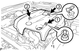
Text in Illustration *1 Tip (Round Portion) Attach the 3 clips in the order shown in the illustration to install the V-bank cover.
Note
-
Securely attach the clips.
-
If the clips are forcibly attached or struck with an object, they may be damaged.
-
Do not apply any oil to the tips (round portions).
-
-
-
INSTALL COOL AIR INTAKE DUCT SEAL
-
Install the cool air intake duct seal with the 7 clips.
-
-
INSTALL ENGINE ROOM SIDE COVER
-
Install the engine room side cover with the 4 clips.
-