ENGINE UNIT INSTALLATION

-
INSTALL ENGINE COOLANT TEMPERATURE SENSOR
Tech Tips
w/ Canister Pump Module:
Perform "Inspection After Repairs" after replacing the engine coolant temperature sensor Click here.
-
Install a new gasket to the engine coolant temperature sensor.
-
Install the engine coolant temperature sensor.
- Torque:
- 20 N*m { 200 kgf*cm, 14 ft.*lbf }
-
Connect the engine coolant temperature sensor connector.
-
-
INSTALL ENGINE OIL PRESSURE SWITCH ASSEMBLY
-
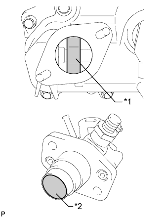
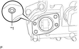
Apply adhesive to 2 or 3 threads of the engine oil pressure switch.
Adhesive Toyota Genuine Adhesive 1324, Three Bond 1324 or equivalent Note
Do not apply adhesive to the oil inlet port of the engine oil pressure switch.
-
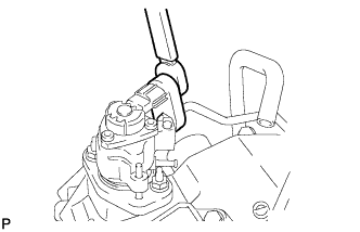
Using a 24 mm deep socket wrench, install the engine oil pressure switch.
- Torque:
- 15 N*m { 153 kgf*cm, 11 ft.*lbf }
Note
Do not start the engine for at least 1 hour after installation.
-
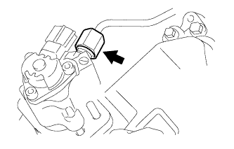
Connect the engine oil pressure switch connector.
-
-
INSTALL ENGINE OIL LEVEL SENSOR
-
Install a new gasket to the engine oil level sensor.
-
Install the engine oil level sensor with the 4 bolts.
- Torque:
- 7.0 N*m { 71 kgf*cm, 62 in.*lbf }
Tech Tips
Be sure to clean the contact surface.
-
Connect the engine oil level sensor connector.
-
-
INSTALL IGNITION COIL ASSEMBLY
Tech Tips
w/ Canister Pump Module:
Perform "Inspection After Repairs" after replacing the ignition coil Click here.
-
Install the 6 ignition coils with the 6 bolts.
- Torque:
- 10 N*m { 102 kgf*cm, 7 ft.*lbf }
-
Connect the 6 ignition coil connectors.
-
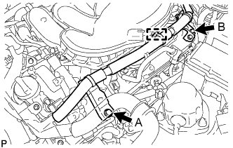
Connect the 2 wire harness brackets with the 2 bolts.
- Torque:
- for bolt A
- 21 N*m { 214 kgf*cm, 15 ft.*lbf }
- for bolt B
- 10 N*m { 102 kgf*cm, 7 ft.*lbf }
-
Connect the wire harness clamp.
-
Connect the wire harness with the 2 nuts.
- Torque:
- 10 N*m { 102 kgf*cm, 7 ft.*lbf }
-
-
INSTALL V-BANK COVER BRACKET SUB-ASSEMBLY
-
Install the V-bank cover bracket with the bolt.
- Torque:
- 10 N*m { 102 kgf*cm, 7 ft.*lbf }
-
-
INSTALL FUEL INJECTOR SEAL
-
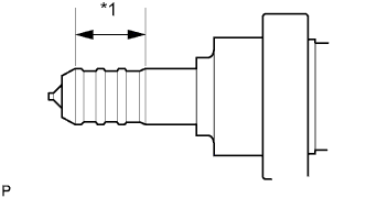
Text in Illustration *1 Clean Area Apply engine conditioner to the injector area shown in the illustration. Using a piece of cloth, clean carbon deposits from the injector and its grooves.
Note
-
Do not clean the tip of the injector.
-
Do not use a wire brush to clean the injector.
-
If an injector is dropped or the tips of the injectors are struck, replace it with a new one.
-
-
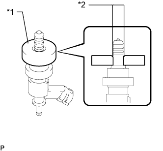
Text in Illustration *1 SST (Guide) *2 Tapered Inner Portion Apply engine oil to the injector contact surface of SST (guide). Then attach SST (guide) to the injector with the tapered inner portion facing the tip of the injector, as shown in the illustration.
- SST
- 09260-39015 ( 09268-03020 )
-
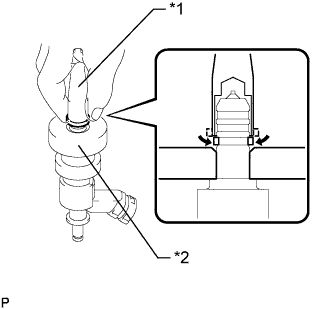
Text in Illustration *1 Fuel Injector Seal *2 SST (Holder) *a CORRECT *b INCORRECT Install a new injector seal to SST (holder).
- SST
- 09260-39015 ( 09268-03010 )
Note
Be careful not to install the injector seal to SST (holder) at an angle. Doing so will stretch the seal and correcting this problem is very complicated.
-
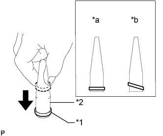
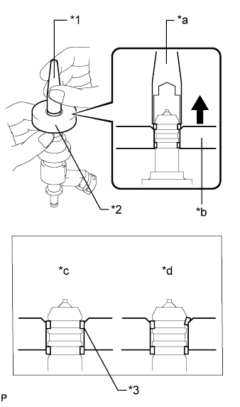
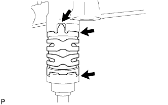
Text in Illustration *1 SST (Holder) *2 SST (Guide) Install SST (holder with injector seal) to the tip of the injector. Slide the seal downward into the injector groove (injector connector side) with your fingers, as shown in the illustration.
- SST
- 09260-39015 ( 09268-03010, 09268-03020 )
Tech Tips
Check that the seal covers the circumference of the injector groove as shown in the illustration.
-
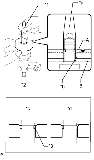
Text in Illustration *1 SST (Holder) *2 SST (Guide) *3 Injector Seal *a Gently Press *b Slowly Slide *c CORRECT *d INCORRECT Using SST (holder), gently press downward on the injector seal (injector connector side). Then slowly slide SST (guide) toward the injector tip to settle the seal into the injector groove.
- SST
- 09260-39015 ( 09268-03010, 09268-03020 )
Note
Be careful that the seal is not pinched between SST (guide) and the injector groove. Replace the seal if it becomes damaged.
Tech Tips
-
When using SST (guide) to settle the seal into the groove, SST (guide) only needs to be slid upward to the position labeled A in the illustration.
-
After using SST (guide) to settle the seal into the groove, return SST (guide) to its position labeled B in the illustration.
-
Text in Illustration *1 Fuel Injector Seal *2 SST (Holder) *a CORRECT *b INCORRECT Install a new injector seal to the injector groove (injector tip side) as shown in the illustration.
- SST
- 09260-39015 ( 09268-03010 )
-
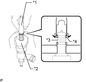
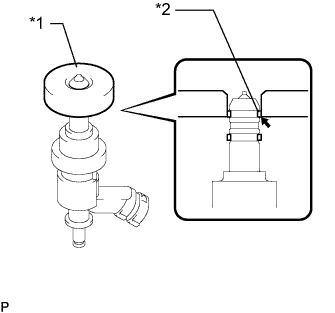
Text in Illustration *1 SST (Holder) *2 SST (Guide) *3 Welded Groove *4 Injector Seal Check that the seal covers the circumference of the injector groove as shown in the illustration.
- SST
- 09260-39015 ( 09268-03010, 09268-03020 )
Note
Make sure that the seal does not slip into the welded groove of the injector shown in the illustration. If it does, replace it with a new one.
-
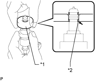
Text in Illustration *1 SST (Guide) *2 Injector Seal Slowly slide SST (guide) toward the tip of the injector. When the injector contact surface of SST (guide) aligns with the seal (injector connector side) as shown in the illustration, hold the position for 5 seconds or more to fully align the seal into the injector groove.
- SST
- 09260-39015 ( 09268-03020 )
Note
Be careful that the seal is not pinched between SST (guide) and the injector groove. Replace the seal if it becomes damaged.
Tech Tips
-
Set SST (guide) so that its bottom surface and seal are flush.
-
If there is difficulty in sliding SST upward, slowly wiggle it from side to side while sliding it up the injector little by little.
-
Text in Illustration *1 SST (Holder) *2 SST (Guide) *3 Injector Seal *a Gently Press *b Slide *c CORRECT *d INCORRECT Using SST (holder), gently press downward on the injector seal (injector tip side). Then slowly slide SST (guide) toward the injector tip to settle the seal into the injector groove.
- SST
- 09260-39015 ( 09268-03010, 09268-03020 )
Note
Be careful that the seal is not pinched between SST (guide) and the injector groove. Replace the seal if it becomes damaged.
-
Text in Illustration *1 SST (Guide) *2 Injector Seal Slowly slide SST (guide) toward the tip of the injector. When the injector contact surface of SST (guide) aligns with the seal (injector tip side) as shown in the illustration, hold the position for 5 seconds or more to fully align the seal into the injector groove.
- SST
- 09260-39015 ( 09268-03020 )
Note
Be careful that the seal is not pinched between SST (guide) and the injector groove. Replace the seal if it becomes damaged.
Tech Tips
-
Set SST (guide) so that its bottom surface and the seal are flush.
-
If there is difficulty in sliding SST upward, slowly wiggle it from side to side while sliding it up the injector little by little.
-
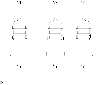
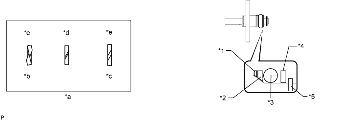
Text in Illustration *a Normal *b Protruding *c Deformed *d CORRECT *e INCORRECT After installing the seals, check that they are not scratched, deformed or protruding from the injector groove.
Note
If a seal is scratched, deformed or protruding from the groove, replace it with a new one.
-
-
INSTALL FUEL INJECTOR ASSEMBLY
Tech Tips
w/ Canister Pump Module:
Perform "Inspection After Repairs" after replacing the fuel injector assembly Click here.
-
Install a new O-ring, new backup rings (No. 1, No. 2 and No. 3) and new E-ring to the fuel injector as shown in the illustration.
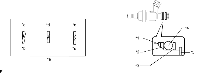
Text in Illustration *1 No. 1 Backup Ring *2 No. 2 Backup Ring *3 No. 3 Backup Ring *4 O-Ring *5 E-Ring - - *a Alignment Opening *b Overlapped *c Stretched *d CORRECT *e INCORRECT - - Note
-
Check that there is no foreign matter or damaged areas in the O-ring groove of the injector.
-
Check that the No. 1 and No. 2 backup rings are installed in the correct direction.
-
Make sure that the backup rings and O-ring are installed in the correct order.
-
Check that the alignment openings of the backup rings are not overlapped or stretched as shown in the illustration.
-
After installing the O-ring, check that it is not contaminated with foreign matter and is not damaged.
-
-
Install the injector nozzle holder clamp.
-
Apply gasoline to the O-ring. Install the nozzle holder clamp by aligning the protruding part of the clamp to the notch of the delivery pipe.
Note
-
Make sure that there is no gap between the delivery pipe and clamp.
-
Check that there is no foreign matter or damage to the injector insertion hole of the delivery pipe.
-
Insert the injector straight into the delivery pipe without tilting it.
-
-
-
INSTALL FUEL DELIVERY PIPE SUB-ASSEMBLY
-
Install a new injector vibration insulator to the cylinder head.
-
Apply lubricant to the installation hole of the injector.
-
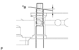
Text in Illustration *1 Nut can be attached Insert the stud bolt into the fuel delivery pipe until the screw threads protrude enough so that a nut can be attached.
Note
-
If an injector is dropped or the tips of the injectors are struck, replace it with a new one.
-
Check that there is no foreign matter or damage to the injector insertion hole of the delivery pipe.
-
When inserting the fuel delivery pipe, push it in evenly without tilting it.
-
-
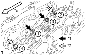
Text in Illustration *1 Nut *2 Bolt *a Front Install the No. 1 fuel delivery pipe by uniformly tightening the 2 bolts and 2 nuts in several passes in the order shown in the illustration.
- Torque:
- 26 N*m { 265 kgf*cm, 19 ft.*lbf }
-
Connect the 3 injector connectors and 2 wire harness clamps.
-
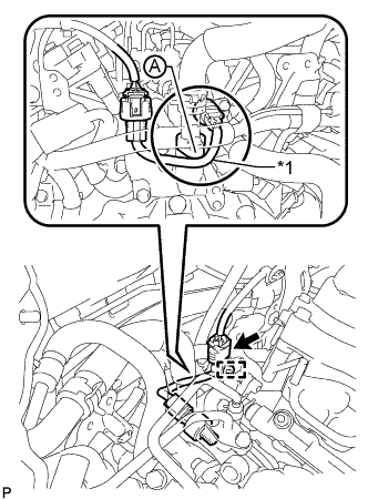
Text in Illustration *1 Wire Harness Connect the fuel pressure sensor connector and attach the clamp.
Note
-
Make sure the wire harness of the fuel pressure sensor passes under the area labeled A as shown in the illustration.
-
Do not pull the wire harness of the fuel pressure sensor excessively.
-
-
-
INSTALL NO. 2 FUEL DELIVERY PIPE SUB-ASSEMBLY
-
Install new injector vibration insulators to the cylinder head.
-
Apply lubricant to the installation holes of the injectors.
-
Text in Illustration *a Nut can be attached Insert the stud bolt into the delivery pipe until the screw threads protrude enough so that a nut can be attached.
Note
-
If an injector is dropped or the tips of the injectors are struck, replace it with a new one.
-
Check that there is no foreign matter or damage to the injector insertion hole of the delivery pipe.
-
When inserting the fuel delivery pipe, push it in evenly without tilting it.
-
-
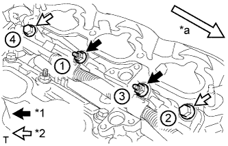
Text in Illustration *1 Nut *2 Bolt *a Front Install the No. 2 fuel delivery pipe by uniformly tightening the 2 bolts and 2 nuts in several passes in the order shown in the illustration.
- Torque:
- 26 N*m { 265 kgf*cm, 19 ft.*lbf }
-
Connect the 3 injector connectors and 3 wire harness clamps.
-
-
INSTALL NO. 3 FUEL PIPE SUB-ASSEMBLY
-
Install new O-rings, new backup rings (No. 1, No. 2 and No. 3) and new E-rings to the No. 3 fuel pipe as shown in the illustration.
Text in Illustration *1 No. 1 Backup Ring *2 No. 2 Backup Ring *3 O-Ring *4 No. 3 Backup Ring *5 E-Ring - - *a Alignment Opening *b Overlapped *c Stretched *d CORRECT *e INCORRECT - - Note
-
Check that there is no foreign matter or damaged areas in the O-ring groove of the injector.
-
Check that the No. 1 and No. 2 backup rings are installed in the correct direction.
-
Make sure that the backup rings and O-ring are installed in the correct order.
-
Check that the alignment openings of the backup rings are not overlapped or stretched as shown in the illustration.
-
After installing the O-ring, check that it is not contaminated with foreign matter and is not damaged.
-
Check that the fuel pipe installation end is not contaminated with foreign matter and is not damaged.
-
-
Text in Illustration *a No Gap 
Front Apply gasoline to the O-ring.
-
Press the fuel pipe and delivery pipe together by hand until there is no gap between them. Then install the No. 3 fuel pipe with the 4 bolts.
- Torque:
- 10 N*m { 102 kgf*cm, 7 ft.*lbf }
Note
Do not install the No. 3 fuel pipe at an angle.
-
-
INSTALL NO. 2 FUEL PIPE SUB-ASSEMBLY
-
Install a new O-ring, new backup rings (No. 1, No. 2 and No. 3) and new E-ring to the No. 2 fuel pipe as shown in the illustration.
Text in Illustration *1 No. 1 Backup Ring *2 No. 2 Backup Ring *3 O-Ring *4 No. 3 Backup Ring *5 E-Ring - - *a Alignment Opening *b Overlapped *c Stretched *d CORRECT *e INCORRECT - - Note
-
Check that there is no foreign matter or damaged areas in the O-ring groove of the injector.
-
Check that the No. 1 and No. 2 backup rings are installed in the correct direction.
-
Make sure that the backup rings and O-ring are installed in the correct order.
-
Check that the alignment openings of the backup rings are not overlapped or stretched as shown in the illustration.
-
After installing the O-ring, check that it is not contaminated with foreign matter and is not damaged.
-
Check that the No. 3 fuel pipe installation end is not contaminated with foreign matter and is not damaged.
-
-
Apply gasoline to the O-ring and connect the fuel pipe to the delivery pipe.
Note
-
Do not install the No. 2 fuel pipe at an angle.
-
Do not install the bolt at this time.
-
-
-
INSTALL FUEL PUMP ASSEMBLY
Tech Tips
w/ Canister Pump Module:
Perform "Inspection After Repairs" after replacing the fuel pump assembly Click here.
-
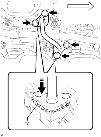
Text in Illustration *1 Camshaft *2 Oil Collector *3 Fuel Pump *a CORRECT *b INCORRECT Turn the crankshaft until the flat of the cam is facing the cylinder head cover's fuel pump attachment hole, as shown in the illustration.
Tech Tips
When installing the fuel pump by following the procedure described above: By not using the crankshaft pointed side to push up the pump activation surface, it is easier to install the fuel pump and No. 2 fuel pipe later.
-
Pour 30 cc of engine oil through the cylinder head cover's fuel pump attachment hole into the cylinder head oil collector.
-
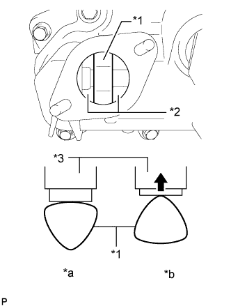
Text in Illustration *1 Camshaft *2 Pump Lifter Apply a coat of engine oil to the pump activation cam and pump lifter part.
-
Text in Illustration *1 Metal Eyelets Install a new fuel pump insulator to the cylinder head cover. Then pass the 2 stud bolts through the holes of the fuel pump and insulator.
Note
Install the insulator so that the open sides of the metal eyelets are facing outward as shown in the illustration.
-
Temporarily install the No. 2 fuel pipe sub-assembly to the fuel pump assembly.
Note
Be careful not to damage the sealing surface of the fuel pipe when temporarily installing the fuel pipe.
-
Install the 2 nuts and tighten them in several passes.
- Torque:
- 25 N*m { 255 kgf*cm, 18 ft.*lbf }
-
-
CONNECT NO. 2 FUEL PIPE SUB-ASSEMBLY
-
Install the No. 2 fuel pipe to the delivery pipe with the 2 bolts.
- Torque:
- 10 N*m { 102 kgf*cm, 7 ft.*lbf }
-
Using a 19 mm union nut wrench, connect the fuel pipe.
- Torque:
- 30 N*m { 306 kgf*cm, 22 ft.*lbf }
Tech Tips
The torque shown above should be used for tightening without using union nut wrench. When the union nut wrench is used for tightening, the torque should be calculated based on the length of the union nut wrench Click here.
-
Connect the connector to the fuel pump.
-
-
INSTALL NO. 1 FUEL PIPE SUB-ASSEMBLY
-
Install the No. 1 fuel pipe sub-assembly with the 2 bolts.
- Torque:
- 10 N*m { 102 kgf*cm, 7 ft.*lbf }
-
Connect the 2 fuel hoses.
-
Connect the No. 2 fuel hose to the No. 1 fuel pipe sub-assembly.
-
-
INSTALL FUEL PRESSURE PULSATION DAMPER ASSEMBLY
-
Apply a light coat of engine oil to the threads and gasket seating surface of the fuel pressure pulsation damper assembly.
-
Install 2 new gaskets, the fuel tube and fuel pressure pulsation damper to the fuel pump.
-
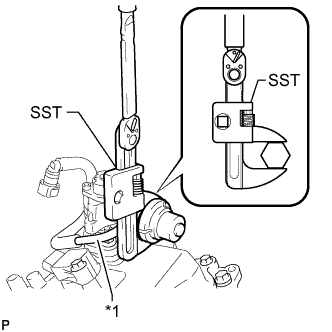
Text in Illustration *1 Fuel Tube Sub-assembly Using SST, tighten the fuel pressure pulsation damper to the fuel pump.
- SST
- 09922-10010
- Torque:
- without SST
- 40 N*m { 408 kgf*cm, 30 ft.*lbf }
- with SST
- 28 N*m { 281 kgf*cm, 20 ft.*lbf }
Tech Tips
-
The "with SST" torque value is effective when using a torque wrench with a fulcrum length of 300 mm (11.81 in.).
-
The torque shown above should be used for tightening without using SST. When SST is used for tightening, the torque should be calculated based on the length of SST Click here.
-
-
INSTALL NO. 3 WATER BY-PASS PIPE
-
Connect the 2 hoses, and install the bolt and No. 3 water by-pass pipe.
- Torque:
- 10 N*m { 102 kgf*cm, 7 ft.*lbf }
-
-
INSTALL FUEL TUBE SUB-ASSEMBLY
-
Install the 2 bolts and fuel tube sub-assembly.
- Torque:
- 10 N*m { 102 kgf*cm, 7 ft.*lbf }
-
-
INSTALL INTAKE MANIFOLD
-
Install 2 new gaskets and the intake manifold with the 4 bolts and 4 nuts.
- Torque:
- 21 N*m { 214 kgf*cm, 15 ft.*lbf }
-
-
INSTALL NO. 2 SURGE TANK STAY
-
Install the No. 2 surge tank stay with the bolt.
- Torque:
- 21 N*m { 214 kgf*cm, 15 ft.*lbf }
-
-
INSTALL INTAKE AIR SURGE TANK ASSEMBLY
Note
Do not apply oil to the bolts for the parts listed below:
Part Intake air surge tank assembly and intake manifold Surge tank stay and intake air surge tank assembly
-
Install a new gasket to the intake air surge tank assembly.
-
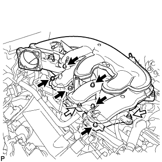
Using a 5 mm long hexagon socket wrench, install the 6 bolts.
Text in Illustration 
Bolt Nut - Torque:
- 18 N*m { 184 kgf*cm, 13 ft.*lbf }
-
Install the intake air surge tank assembly with the 2 nuts.
- Torque:
- 16 N*m { 163 kgf*cm, 12 ft.*lbf }
-
Install the No. 2 surge tank stay with the bolt.
- Torque:
- 21 N*m { 214 kgf*cm, 15 ft.*lbf }
-
Install the No. 3 water by-pass pipe with the bolt.
- Torque:
- 10 N*m { 102 kgf*cm, 7 ft.*lbf }
-
for LHD:
Connect the 4 wire harness clamps.
-
for RHD:
Connect the 5 wire harness clamps.
-
Connect the PCV hose, union to check valve hose and water by-pass hose.
-
-
INSTALL THROTTLE WITH MOTOR BODY ASSEMBLY
-
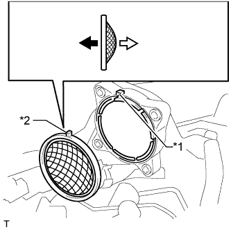
Text in Illustration *1 Groove *2 Protrusion Throttle Body Side Intake Air Surge Tank Side Install a new gasket to the intake air surge tank.
Tech Tips
Align the protrusion of the gasket on the intake air surge tank.
-
Connect the 2 water by-pass hoses to the throttle body.
-
Install the throttle body with the 4 bolts.
- Torque:
- 10 N*m { 102 kgf*cm, 7 ft.*lbf }
Tech Tips
w/ Canister Pump Module:
Perform "Inspection After Repairs" after replacing the throttle body with motor Click here.
-
Connect the throttle motor connector.
-
-
INSTALL INJECTOR DRIVER
Note
-
Be careful not to drop or strike the injector driver.
-
The injector driver is grounded at the bolt and nut. To ensure that it is grounded, clean all oil and foreign matter from the installation areas of the injector driver and engine before installing the injector driver.
-
Install the injector driver with the bolt and 2 nuts.
- Torque:
- 10 N*m { 102 kgf*cm, 7 ft.*lbf }
-
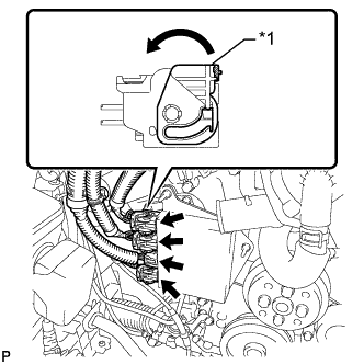
Text in Illustration *1 Lock Lever Connect the 4 connectors to the injector driver. Move the lock levers in the direction indicated by the arrow to lock the 3 connectors.
-
-
INSTALL ENGINE WIRE
-
INSTALL WATER PUMP PULLEY
-
Temporarily install the pulley with the 4 bolts.
-
Using SST, hold the pulley and tighten the 4 bolts.
- SST
- 09960-10010 ( 09962-01000, 09963-00700 )
- Torque:
- 21 N*m { 214 kgf*cm, 15 ft.*lbf }
-
-
INSTALL V-RIBBED BELT TENSIONER ASSEMBLY
-
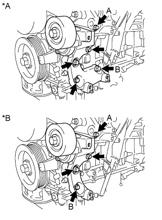
Text in Illustration *A for 2WD *B for AWD Temporarily install the V-ribbed belt tensioner assembly with the bolt A and bolt B.
-
Temporarily install the other bolts.
-
for 2WD:
Tighten the 5 bolts to install the V-ribbed belt tensioner assembly.
- Torque:
- 43 N*m { 439 kgf*cm, 32 ft.*lbf }
-
for AWD:
Tighten the 4 bolts to install the V-ribbed belt tensioner assembly.
- Torque:
- 43 N*m { 439 kgf*cm, 32 ft.*lbf }
-
-
INSTALL FRONT NO. 1 ENGINE MOUNTING BRACKET LH
-
Install the front No. 1 engine mounting bracket LH with the 4 bolts.
- Torque:
- 43 N*m { 439 kgf*cm, 32 ft.*lbf }
-
Connect the 2 clamps.
-
-
INSTALL FRONT NO. 1 ENGINE MOUNTING BRACKET RH
-
Install the front No. 1 engine mounting bracket RH with the 4 bolts.
- Torque:
- 43 N*m { 439 kgf*cm, 32 ft.*lbf }
-
-
INSTALL COOLER COMPRESSOR ASSEMBLY
-
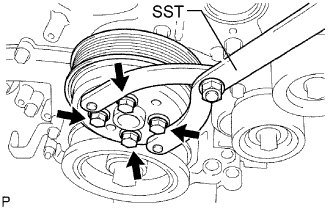
Using an E8 "torx" socket, install the cooler compressor assembly with the stud bolt.
- Torque:
- 10 N*m { 102 kgf*cm, 7 ft.*lbf }
-
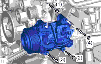
Install the cooler compressor assembly with the 3 bolts and nut.
- Torque:
- for bolt
- 25 N*m { 250 kgf*cm, 18 ft.*lbf }
- for nut
- 25 N*m { 250 kgf*cm, 18 ft.*lbf }
Note
Tighten the bolts in the order shown in the illustration to install the cooler compressor assembly.
-
-
INSTALL GENERATOR ASSEMBLY
-
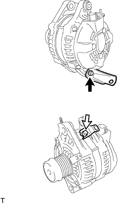
Install the 2 brackets with the 2 bolts.
- Torque:
- for bolt A
- 20 N*m { 204 kgf*cm, 15 ft.*lbf }
- for bolt B
- 10 N*m { 102 kgf*cm, 7 ft.*lbf }
Text in Illustration Bolt A Bolt B -
Install the generator with the 2 bolts.
- Torque:
- 43 N*m { 438 kgf*cm, 32 ft.*lbf }
-
Install the bracket with the nut.
- Torque:
- 20 N*m { 204 kgf*cm, 15 ft.*lbf }
-
Connect the generator wire to terminal B with the nut.
- Torque:
- 9.8 N*m { 100 kgf*cm, 87 in.*lbf }
-
Install the terminal cap.
-
Attach the 2 clamps, and connect the generator connector to the generator.
-
Connect the connector to the cooling fan ECU.
-
-
INSTALL NO. 2 IDLER PULLEY SUB-ASSEMBLY
-
Install the pulley and cover plate with the bolt.
- Torque:
- 43 N*m { 438 kgf*cm, 32 ft.*lbf }
-
-
INSTALL NO. 1 ENGINE COVER
-
Install the No. 1 engine cover with the 3 clips.
-
-
INSTALL NO. 2 ENGINE COVER
-
Install the No. 2 engine cover with the 3 clips.
-
Connect the clamp.
-
-
INSTALL FAN AND GENERATOR V BELT
-
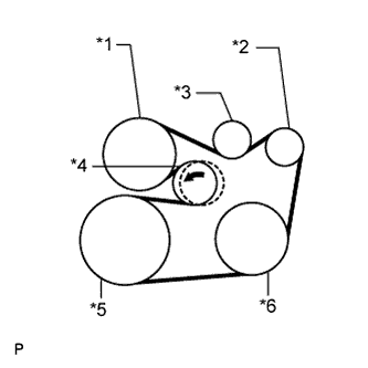
Text in Illustration *1 Engine Water Pump *2 Generator *3 Idler *4 Tensioner *5 Crankshaft *6 A/C Compressor Set the V belt onto every part.
-
While turning the belt tensioner counterclockwise, remove the bar.
Note
-
Put the backside of the V belt on the tensioner pulley and idler pulley.
-
Check that the V belt is properly set to each pulley.
-
-
If it is difficult to install the V belt, perform the following procedure.
-
Put the V belt on every part except the tensioner pulley.
-
Put the V belt on the tensioner pulley while turning the belt tensioner counterclockwise.
Note
-
Put the backside of the V belt on the tensioner pulley and idler pulley.
-
Check that the V belt is properly set to each pulley.
-
-
-
Check that the belt fits properly in the ribbed grooves.
Tech Tips
Make sure to check by hand that the belt has not slipped out of the grooves on the bottom of the pulley.
-