AIR FUEL RATIO SENSOR INSTALLATION

-
INSTALL AIR FUEL RATIO SENSOR
-

Text in Illustration *A for 2WD *B for AWD *1 Fulcrum Length for Bank 2 Sensor 1:
Using SST, install the air fuel ratio sensor to the exhaust manifold LH.
- SST
- 09224-00010
- Torque:
- without SST
- 44 N*m { 449 kgf*cm, 32 ft.*lbf }
- with SST
- 40 N*m { 408 kgf*cm, 30 ft.*lbf }
Tech Tips
-
Use a torque wrench with a fulcrum length of 300 mm (11.8 in.). When using a torque wrench with a fulcrum length that is not 300 mm (11.8 in.), calculate the torque specification for the torque wrench and SST based on the "without SST" torque specification Click here.
-
Make sure SST and the wrench are connected in a straight line.
-

Text in Illustration *1 Fulcrum Length for Bank 1 Sensor 1:
Using SST, install the air fuel ratio sensor to the exhaust manifold RH.
- SST
- 09224-00010
- Torque:
- without SST
- 44 N*m { 449 kgf*cm, 32 ft.*lbf }
- with SST
- 40 N*m { 408 kgf*cm, 30 ft.*lbf }
Tech Tips
-
Use a torque wrench with a fulcrum length of 300 mm (11.8 in.). When using a torque wrench with a fulcrum length that is not 300 mm (11.8 in.), calculate the torque specification for the torque wrench and SST based on the "without SST" torque specification Click here.
-
Make sure SST and the wrench are connected in a straight line.
-
Attach the 2 wire harness clamps.
-
Connect the air fuel ratio sensor connector.
-
-
CONNECT RELAY BLOCK ASSEMBLY
-
Connect the relay block assembly with the 2 bolts and nut.
- Torque:
- for bolt
- 8.0 N*m { 82 kgf*cm, 71 in.*lbf }
- for nut
- 13 N*m { 127 kgf*cm, 9 ft.*lbf }
-
-
INSTALL NO. 4 ENGINE WIRE (for LHD)
-
Connect the No. 4 engine wire to the engine room No. 1 junction block. Then, install it with the nut.
- Torque:
- 11 N*m { 107 kgf*cm, 8 ft.*lbf }
-
Attach the 2 wire harness clamps.
-
Install the engine room No. 1 relay block cover.
-
-
INSTALL NO. 4 ENGINE WIRE (for RHD)
-
Connect the No. 4 engine wire to the engine room No. 1 junction block. Then, install it with the nut.
- Torque:
- 11 N*m { 107 kgf*cm, 8 ft.*lbf }
-
Attach the wire harness clamp.
-
Install the engine room No. 1 relay block cover.
-
-
INSTALL BATTERY TRAY (for LHD)
-
Install the battery tray with the 2 bolts.
- Torque:
- 5.4 N*m { 55 kgf*cm, 48 in.*lbf }
-
Connect the fuel pipe clamp.
-
-
INSTALL BATTERY TRAY (for RHD)
-
Install the battery tray with the 2 bolts.
- Torque:
- 5.4 N*m { 55 kgf*cm, 48 in.*lbf }
-
-
INSTALL AIR CLEANER CAP WITH AIR CLEANER HOSE
-
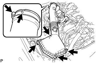
Install the air cleaner cap with air cleaner hose assembly with the 4 clamps and hose clamp.
- Torque:
- 4.0 N*m { 41 kgf*cm, 35 in.*lbf }
Tech Tips
Fit the protrusion on the air cleaner hose into the hole of the hose clamp on the throttle valve side.
-
Connect the VSV hose to the air cleaner hose.
-
for RHD:
Connect the union to check valve hose.
-
Connect the mass air flow meter connector and clamp to the air cleaner.
-
-
CONNECT NO. 2 VENTILATION HOSE
-
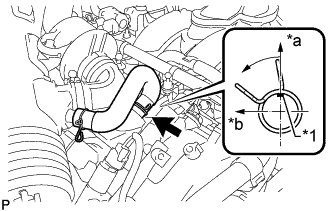
Text in Illustration *1 Paint Mark *a Top *b Front Connect the ventilation hose to the cylinder head cover with the clamp.
Tech Tips
Make sure the direction of the clip is as shown in the illustration.
-
-
INSTALL V-BANK COVER SUB-ASSEMBLY
-
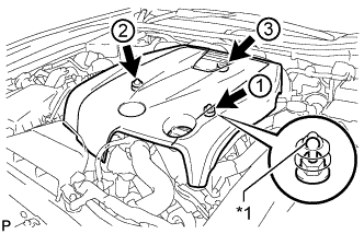
Text in Illustration *1 Tip (Round Portion) Attach the 3 clips in the order shown in the illustration to install the V-bank cover.
Note
-
Securely attach the clips.
-
If the clips are forcibly attached or struck with an object, they may be damaged.
-
Do not apply any oil to the tips (round portions).
-
-
-
INSTALL COOL AIR INTAKE DUCT SEAL
-
Install the cool air intake duct seal with the 7 clips.
-
-
INSTALL ENGINE ROOM SIDE COVER
-
Install the engine room side cover with the 4 clips.
-
-
INSTALL POWER STEERING ECU ASSEMBLY
-
INSPECT FOR EXHAUST GAS LEAK
If gas is leaking, tighten the areas necessary to stop the leak. Replace damaged parts as necessary.