REAR SUSPENSION MEMBER REMOVAL

-
RELEASE PARKING BRAKE
-
With the engine switch on (IG), operate the electric parking brake switch to release the parking brake. Then turn the engine switch off.
Tech Tips
If the parking brake cannot be released, use the luggage compartment's parking brake release tool to manually release the parking brake.
-
-
PRECAUTION
Note
After turning the engine switch off, waiting time may be required before disconnecting the cable from the battery terminal. Therefore, make sure to read the disconnecting the cable from the battery terminal notice before proceeding with work Click here.
-
DISCONNECT CABLE FROM NEGATIVE BATTERY TERMINAL
CAUTION:
Wait at least 90 seconds after disconnecting the cable from the negative (-) battery terminal to disable the SRS system.
Note
When disconnecting the cable, some systems need to be initialized after the cable is reconnected Click here.
-
REMOVE REAR WHEEL
-
REMOVE ECU BRACKET
-
DISCONNECT WIRE HARNESS
-
for Type A, B:
-
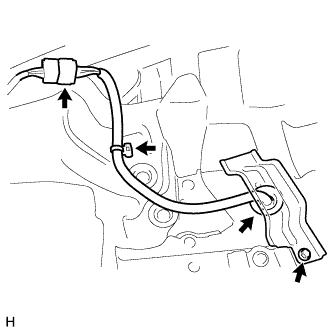
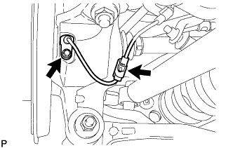
Remove the bolt and parking brake plunger protector.
-
Disconnect the connector.
-
Disconnect the harness clamp.
-
Detach the trunk interior electric parking brake actuator grommet.
-
-
for Type C:
-
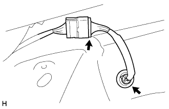
Detach the trunk interior electric parking brake actuator grommet and disconnect the connector.
-
-
-
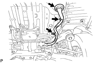
REMOVE NO. 1 FLOOR UNDER COVER
-
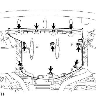
Remove the 4 clips, 6 nuts and No. 1 floor under cover.
-
-
DISCONNECT PARKING BRAKE CABLE
-
REMOVE PARKING BRAKE CABLE HEAT INSULATOR
-
for Type B, C:
Remove the 2 nuts and parking brake cable heat insulator.
-
-
REMOVE ELECTRIC PARKING BRAKE ACTUATOR CAP
-
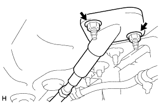
for Type A:
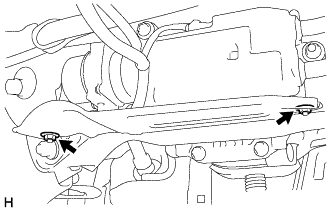
Remove the 2 nuts and electric parking brake actuator cap.
-
for Type B:
-
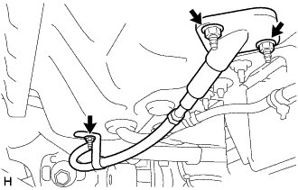
Remove the 2 nuts and electric parking brake actuator cap.
-
Remove the nut and cable support bracket.
-
-
for Type C:
Remove the 2 nuts and electric parking brake actuator cap.
-
-
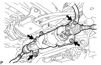
REMOVE PROPELLER WITH CENTER BEARING SHAFT ASSEMBLY
-
for 2GR-FSE 2WD:
-
for 2GR-FSE AWD:
-
for 4GR-FSE:
-
-
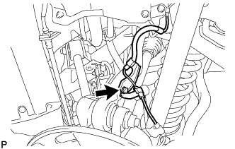
REMOVE REAR HEIGHT CONTROL SENSOR SUB-ASSEMBLY
-
Remove the nut and rear height control link.
-
Remove the 2 bolts and rear height control sensor sub-assembly LH.
-
Detach the clamp.
-
Disconnect the connector.
-
-
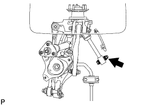
DISCONNECT REAR SPEED SENSOR LH
-
Remove the 2 bolts and disconnect the rear speed sensor from the rear axle assembly.
-
-
DISCONNECT REAR SPEED SENSOR RH
Tech Tips
Use the same procedure described for the LH side.
-
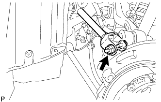
REMOVE REAR AXLE SHAFT NUT LH
-
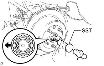
Using SST and a hammer, release the staked part of the axle shaft nut.
- SST
- 09930-00010
Note
Release the staked part of the nut completely, otherwise the screw of the drive shaft may be damaged.
-
While applying the brakes, remove the rear axle shaft nut.
-
-
REMOVE REAR AXLE SHAFT NUT RH
Tech Tips
Use the same procedure described for the LH side.
-
REMOVE PARKING BRAKE
-
REMOVE TOE CONTROL LINK SUB-ASSEMBLY LH (w/o DYNAMIC REAR STEERING)
-
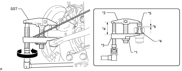
Remove the nut on the rear axle carrier side.
-
Install 2 spacers (SST spacer B) to the toe control link so that there is a space of approximately 1 mm (0.0394 in.) between the link and spacers.
- SST
- 09960-20010 ( 09961-02060 )
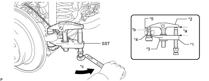
Text in Illustration *1 Claw *2 Body *3 Nut *4 Spacer *5 SST (Spacer B) - - *a Parallel *b Space of approx. 1 mm *c Turn - - Note
-
Make sure to install the spacers (SST spacer B) as the axle carrier spacer may shift.
-
As SST may become damaged, make sure the space between the arm and spacers is not less than 1 mm (0.0394 in.).
-
Using SST, disconnect the toe control link from the rear axle assembly.
- SST
- 09960-20010 ( 09961-02010 )
CAUTION:
Apply grease to the threads and end of the SST bolt.
Note
-
Do not damage the dust cover.
-
As the dust cover may be damaged, adjust SST with the center nut so that the body and claw are parallel.
-
Make sure to tie the string of SST to the vehicle to prevent SST from dropping.
-
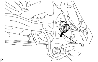
Text in Illustration *a Matchmark Put matchmarks on the rear No. 2 suspension toe adjust plate and rear suspension member.
-
Remove the nut, rear suspension toe adjust cam, rear No. 2 suspension toe adjust plate and toe control link.
-
-
REMOVE TOE CONTROL LINK SUB-ASSEMBLY RH (w/o DYNAMIC REAR STEERING)
-
DISCONNECT REAR STEERING TIE ROD ASSEMBLY LH
-
Remove the clip and castle nut.
-
Install 2 spacers (SST spacer B) to the tie rod assembly LH so that there is a space of approximately 1 mm (0.0397 in.) between the arm and spacers.
- SST
- 09960-20010 ( 09961-02060 )
Text in Illustration *1 Nut *2 Body *3 Claw *4 Spacer *5 Spacer B - - *a Parallel *b 1 mm (0.0394 in.) CAUTION:
Apply MP grease to the threads of SST.
Note
-
Be sure to install the spacers (SST spacer B) as the steering knuckle spacer may shift.
-
As SST may become damaged, make sure the space between the arm and spacers is not 1 mm (0.0397 in.) or less.
-
Using SST, disconnect the tie rod assembly from the steering knuckle.
Note
-
Do not damage the dust cover.
-
As the dust cover may be damaged, adjust SST with the center nut so that the body and claw are parallel.
-
Make sure to tie the string of SST to the vehicle to prevent SST from dropping.
-
If the axle carrier spacer (*4) comes out of position, replace the axle carrier and tie rod.
-
-
-
DISCONNECT REAR STEERING TIE ROD ASSEMBLY RH
Tech Tips
Use the same procedure described for the LH side.
-
REMOVE REAR STEERING LINK ASSEMBLY (w/ DYNAMIC REAR STEERING)
-
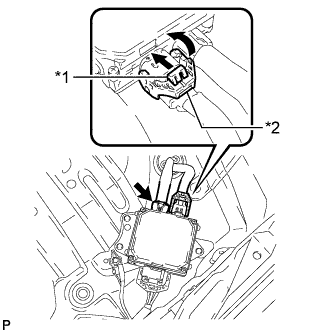
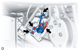
Text in Illustration *1 Lock *2 Claw Disconnect the 2 connectors from the rear steering control ECU.
Tech Tips
Pull up the lock, detach the claw and move the lever to disconnect the connector which uses a lock.
-
Remove the nut and detach the clamp and grommet of the wire harness.
-
Remove the 4 bolts and rear steering link assembly.
Note
Do not drop the rear steering link assembly.
-
-
REMOVE REAR SUSPENSION ARM COVER LH
-
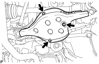
Remove the 3 bolts and rear suspension arm cover from the rear No. 2 suspension arm assembly.
-
-
REMOVE REAR SUSPENSION ARM COVER RH
Tech Tips
Use the same procedure described for the LH side.
-
REMOVE REAR NO. 1 SUSPENSION ARM ASSEMBLY LH
-
Remove the bolt and nut, and disconnect the rear No. 1 suspension arm assembly from the rear axle assembly.
-
Remove the bolt and nut, and then remove the rear No. 1 suspension arm assembly from the rear suspension member.
-
-
REMOVE REAR NO. 1 SUSPENSION ARM ASSEMBLY RH
Tech Tips
Use the same procedure described for the LH side.
-
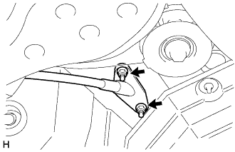
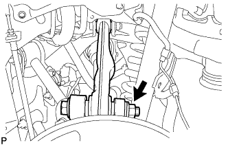
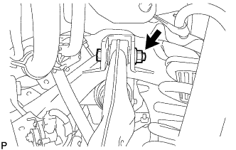
REMOVE REAR STABILIZER LINK ASSEMBLY LH
-
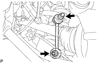
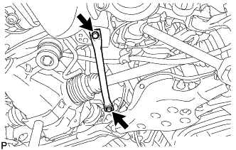
Remove the 2 nuts and rear stabilizer link assembly.
Tech Tips
If the ball joint turns together with the nut, use a 6 mm hexagon wrench to hold the stud bolt.
-
-
REMOVE REAR STABILIZER LINK ASSEMBLY RH
Tech Tips
Use the same procedure described for the LH side.
-
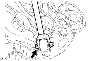
DISCONNECT REAR SHOCK ABSORBER ASSEMBLY LH
-
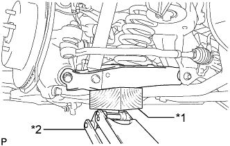
Using a jack and wooden block, jack up the rear No. 2 suspension arm assembly.
Note
-
When jacking up the rear No. 2 suspension arm assembly, be sure to jack it up slowly.
-
Do not jack up the rear No. 2 suspension arm assembly too high as the vehicle may fall.
-
Make sure to perform this operation with the vehicle kept as low as possible.
-
-
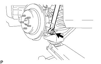
Remove the bolt and nut, and disconnect the rear shock absorber from the rear No. 2 suspension arm assembly.
Note
Hold the nut and remove the bolt.
-
-
DISCONNECT REAR SHOCK ABSORBER ASSEMBLY RH
Tech Tips
Use the same procedure described for the LH side.
-
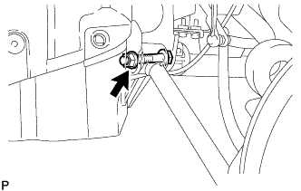
REMOVE REAR SUSPENSION MEMBER BRACE LH
-
Remove the 2 bolts and rear suspension member brace.
-
-
REMOVE REAR SUSPENSION MEMBER BRACE RH
Tech Tips
Use the same procedure described for the LH side.
-
REMOVE REAR NO. 2 SUSPENSION ARM ASSEMBLY LH
-
Loosen the bolt and nut of the rear No. 2 suspension arm on the rear suspension member side.
-
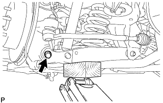
Remove the bolt and nut located on the rear axle assembly of the rear No. 2 suspension arm.
Note
Hold the nut and remove the bolt.
-
Lower the jack gradually to remove the rear coil spring with rear upper coil spring insulator.
-
Remove the bolt, washer and nut, and then remove the rear No. 2 suspension arm assembly from the rear suspension member.
-
Remove the rear lower coil spring insulator from the rear No. 2 suspension arm assembly.
-
-
REMOVE REAR NO. 2 SUSPENSION ARM ASSEMBLY RH
Tech Tips
Use the same procedure described for the LH side.
-
REMOVE REAR NO. 1 UPPER CONTROL ARM ASSEMBLY (for LH Side)
-
Remove the bolt, nut and washer, and disconnect the rear No. 1 upper control arm assembly from the rear axle assembly.
-
Remove the bolt, nut, washer and rear No. 1 upper control arm assembly from the rear suspension member.
-
-
REMOVE REAR NO. 1 UPPER CONTROL ARM ASSEMBLY (for RH Side)
Tech Tips
Use the same procedure described for the LH side.
-
REMOVE REAR UPPER CONTROL ARM ASSEMBLY LH
-
Remove the bolt and disconnect the rear speed sensor from the rear upper control arm.
-
Remove the bolt, nut and washer, and disconnect the rear upper control arm assembly from the rear axle assembly.
-
Remove the bolt, nut, washer and rear upper control arm assembly from the rear suspension member.
-
-
REMOVE REAR UPPER CONTROL ARM ASSEMBLY RH
Tech Tips
Use the same procedure described for the LH side.
-
REMOVE REAR AXLE ASSEMBLY LH
-
Using a plastic-faced hammer, separate the drive shaft from the rear axle carrier sub-assembly.
-
Remove the rear axle assembly.
Note
-
Be careful not to damage the boot.
-
Use a wire or an equivalent to keep the rear drive shaft assembly from hanging down.
-
-
-
REMOVE REAR AXLE ASSEMBLY RH
Tech Tips
Use the same procedure described for the LH side.
-
REMOVE REAR SUSPENSION MEMBER BRACE
-
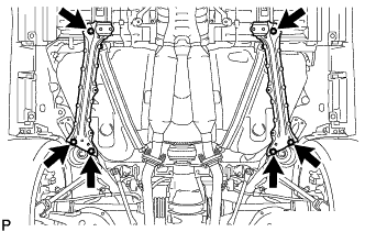
Remove the 6 bolts and 2 rear suspension member braces from the rear suspension member.
-
-
REMOVE REAR SUSPENSION MEMBER SUB-ASSEMBLY
-
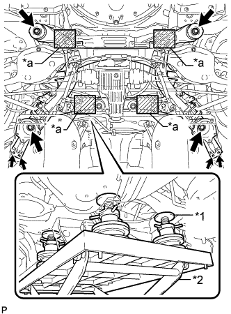
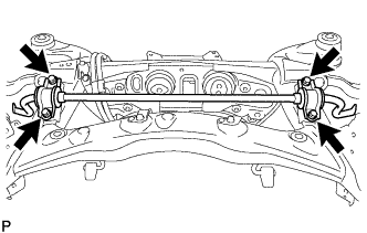
Text in Illustration *1 Attachment *2 Engine Lifter *a Attachment placement location Support the rear suspension member sub-assembly with an engine lifter using 4 attachments or equivalent tools as shown in the illustration.
Note
-
Use the attachments to keep the rear suspension member sub-assembly level.
-
The rear suspension member sub-assembly is a heavy component. Make sure that it is supported securely.
-
-
Remove the 6 bolts, 2 rear suspension member lower stoppers and 2 rear suspension member lower stopper sub-assemblies.
-
Slowly lower the rear suspension member sub-assembly.
Note
When lowering the rear suspension member sub-assembly, be careful not to damage the vehicle body or other components installed on the vehicle.
-
-
REMOVE PARKING BRAKE WITH BRACKET ACTUATOR ASSEMBLY
-
REMOVE REAR DIFFERENTIAL CARRIER ASSEMBLY
-
for 2GR-FSE:
-
for 4GR-FSE:
-
-
REMOVE REAR NO. 1 DIFFERENTIAL MOUNT CUSHION
-
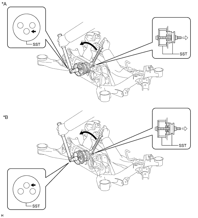
Using SST, remove the rear No. 1 differential mount cushion.
- SST
- 09316-12010
- 09570-24011
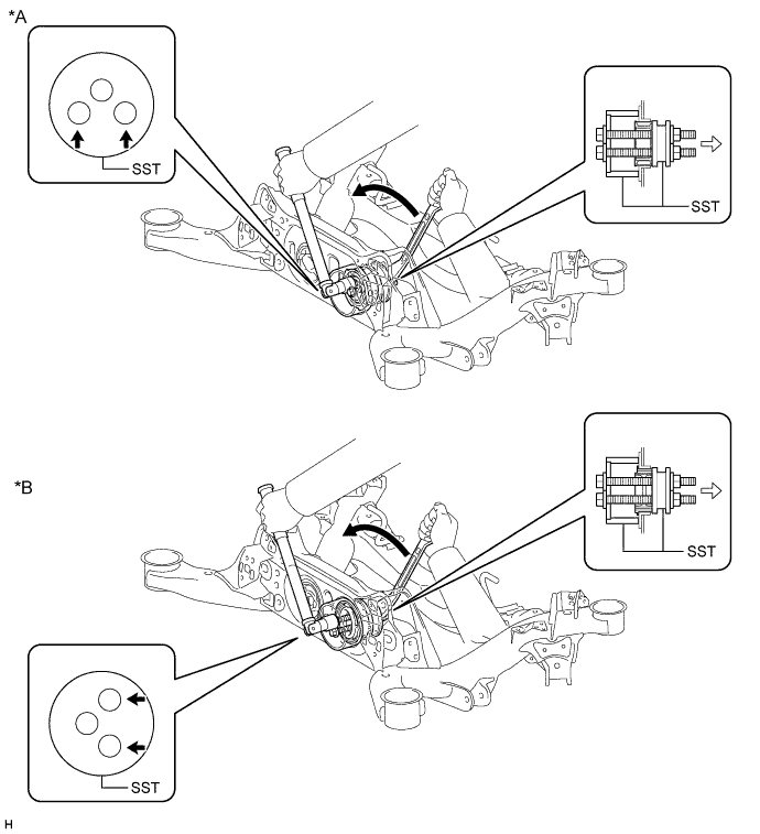
Text in Illustration *A for 2GR-FSE *B for 4GR-FSE 
Front of Vehicle - - Note
-
Do not bring SST into contact with the rear suspension member sub-assembly.
-
Before using SST, apply grease to SST bolts.
-
Set SST in the correct direction.
-
Do not tilt the bolts of SST.
-
Tighten the 2 bolts of SST so that they enter the 2 holes of the rear No. 1 differential mount cushion by an equal amount.
-
Do not reuse the rear No. 1 differential mount cushion.
-
-
REMOVE REAR NO. 2 DIFFERENTIAL MOUNT CUSHION
-
Using SST, remove the rear No. 2 differential mount cushion.
- SST
- 09316-12010
- 09570-24011
Text in Illustration *A for 2GR-FSE *B for 4GR-FSE Front of Vehicle - - Note
-
Do not bring SST into contact with the rear suspension member sub-assembly.
-
Before using SST, apply grease to SST bolt.
-
Set SST in the correct direction.
-
Do not tilt the bolt of SST.
-
Do not reuse the rear No. 2 differential mount cushion.
-
-
REMOVE REAR STABILIZER BAR
-
Remove the 4 bolts, 2 stabilizer brackets, 2 rear stabilizer bushes and rear stabilizer bar.
-
-
REMOVE REAR SUSPENSION MEMBER REAR LOWER STOPPER (for LH Side)
-
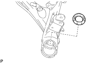
Remove the rear suspension member rear lower stopper from the rear suspension member sub-assembly.
-
-
REMOVE REAR SUSPENSION MEMBER REAR LOWER STOPPER (for RH Side)
Tech Tips
Use the same procedure described for the LH side.
-
REMOVE REAR SUSPENSION MEMBER FRONT BODY MOUNTING CUSHION (for LH Side)
-
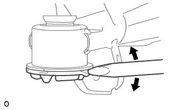
Using a chisel and hammer, bend the rear suspension member rear body mounting cushion rib.
-
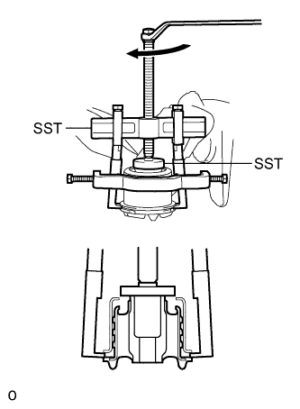
Using SST, remove the rear suspension member front body mounting cushion while applying grease into the clearance between the rear suspension member front body mounting cushion and the rear suspension member sub-assembly.
- SST
- 09950-40011 ( 09951-04020, 09952-04010, 09953-04030, 09954-04020, 09955-04061, 09957-04010, 09958-04011 )
- 09950-60010 ( 09951-00320 )
Note
-
Apply grease to the threads and tip of SST center bolt before use.
-
Be careful as the rear suspension member front body mounting cushion may fly out.
-
The rear suspension member front body mounting cushion cannot be reused.
-
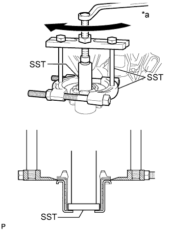
Text in Illustration *a Turn If the outer casing of the rear suspension member front body mounting cushion remains, insert SST between the rear suspension member front body mounting cushion and the rear suspension member sub-assembly, and then remove the outer casing.
- SST
- 09608-06041
- 09950-00020
- 09950-00030
- 09950-60010 ( 09951-00550 )
-
-
REMOVE REAR SUSPENSION MEMBER FRONT BODY MOUNTING CUSHION (for RH Side)
Tech Tips
Use the same procedure described for the LH side.
-
REMOVE REAR SUSPENSION MEMBER REAR UPPER STOPPER (for LH Side)
-
Remove the rear suspension member rear upper stopper from the rear suspension member sub-assembly.
-
-
REMOVE REAR SUSPENSION MEMBER REAR UPPER STOPPER (for RH Side)
Tech Tips
Use the same procedure described for the LH side.
-
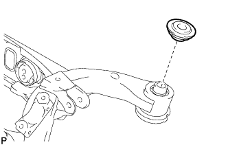
REMOVE REAR SUSPENSION MEMBER REAR BODY MOUNTING CUSHION (for LH Side)
-
Using a chisel and hammer, bend the rear suspension member rear body mounting cushion rib.
-
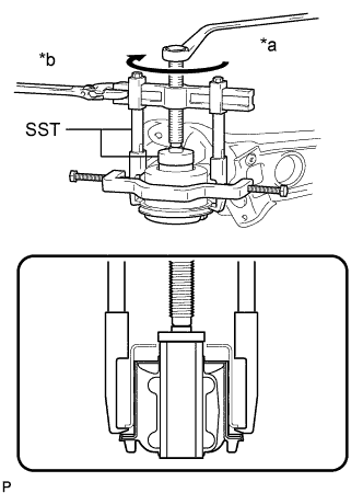
Text in Illustration *a Turn *b Hold Using SST, remove the rear suspension member rear body mounting cushion while applying grease into the clearance between the rear suspension member rear body mounting cushion and the rear suspension member sub-assembly.
- SST
- 09950-40011 ( 09951-04020, 09952-04010, 09953-04030, 09954-04020, 09955-04061, 09957-04010, 09958-04011 )
- 09950-60010 ( 09951-00320 )
Note
-
Apply grease to the threads and tip of SST center bolt before use.
-
Be careful as the rear suspension member rear body mounting cushion may fly out.
-
The rear suspension member rear body mounting cushion cannot be reused.
-
-
REMOVE REAR SUSPENSION MEMBER REAR BODY MOUNTING CUSHION (for RH Side)
Tech Tips
Use the same procedure described for the LH side.