ADAPTIVE VARIABLE SUSPENSION SYSTEM, Diagnostic DTC:C1731, C1732, C1733, C1734

| DTC Code | DTC Name |
|---|---|
| C1731 | Front Damping Force Control Actuator RH Circuit Malfunction |
| C1732 | Front Damping Force Control Actuator LH Circuit Malfunction |
| C1733 | Rear Damping Force Control Actuator RH Circuit Malfunction |
| C1734 | Rear Damping Force Control Actuator LH Circuit Malfunction |
DESCRIPTION
The absorber control actuator switches the damping force depending on the absorber control ECU signals.
| DTC Code | Detection Condition | Trouble Area |
|---|---|---|
| C1731 | Either condition is met:
|
|
| C1732 | Either condition is met:
|
|
| C1733 | Either condition is met:
|
|
| C1734 | Either condition is met:
|
|
-
*: When a short circuit is detected, the absorber control actuator operation is momentarily stopped and then resumes after a certain period of time. A malfunction is detected when a short circuit is detected 8 times consecutively while the absorber control actuator is being powered.
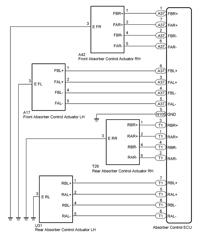
WIRING DIAGRAM
INSPECTION PROCEDURE
Note
-
Before performing troubleshooting, inspect the connectors of related circuits.
-
If DTC C1782 (Power Source Voltage Malfunction) is output at the same time, perform troubleshooting for C1782 first Click here.
-
Before replacing the absorber control ECU, perform all of the following again: 1) symptom simulation Click here; 2) DTC inspection Click here; and 3) GTS inspection (ECU Data List or Active Test Click here. If no malfunctions are found in other areas, replace the absorber control ECU.
-
When the absorber control ECU is replaced, switch to test mode and check that all test mode DTCs are cleared when their respective deletion conditions are met Click here.
PROCEDURE
-
CLEAR DTC
-
Clear the DTCs Click here.
NEXT 
-
-
PERFORM ACTIVE TEST USING GTS (DAMPER STEP)
-
Turn the engine switch off.
-
Connect the GTS to the DLC3.
-
Turn the engine switch on (IG).
-
Turn the GTS on.
-
Enter the following menus: Chassis / Air suspension /Active Test.
Air Suspension Tester Display Test Part Control Range Diagnostic Note Damper Step FR Changes damper step (front RH) 1 to 17 step The shock absorber hardens as the damper step increases. Damper Step FL Changes damper step (front LH) 1 to 17 step The shock absorber hardens as the damper step increases. Damper Step RR Changes damper step (rear RH) 1 to 17 step The shock absorber hardens as the damper step increases. Damper Step RL Changes damper step (rear LH) 1 to 17 step The shock absorber hardens as the damper step increases. -
Check if the absorber control actuator operates to harden the suspension with the GTS.
OK The absorber control actuator operates.
NG 
INSPECT ABSORBER CONTROL ACTUATOR OF WHEEL TO BE INSPECTED Click here
OK
-
-
RECONFIRM DTC
-
Check that the same DTC is output Click here.
Result Result Proceed to DTC is output A DTC is not output B
B 
USE SIMULATION METHOD TO CHECK Click here
A
-
-
INSPECT ABSORBER CONTROL ACTUATOR OF WHEEL TO BE INSPECTED
-
Turn the engine switch off.
-
Remove the absorber control actuator for the front side Click here or rear side Click here.
-
Inspect the absorber control actuator for the front side Click here or rear side Click here.
Result Result Proceed to OK A Front absorber control actuator RH malfunction B Front absorber control actuator LH malfunction C Rear absorber control actuator RH malfunction D Rear absorber control actuator LH malfunction E
B
REPLACE FRONT ABSORBER CONTROL ACTUATOR RH Click here
C
REPLACE FRONT ABSORBER CONTROL ACTUATOR LH Click here
D
REPLACE REAR ABSORBER CONTROL ACTUATOR RH Click here
E
REPLACE REAR ABSORBER CONTROL ACTUATOR LH Click here
A
-
-
CHECK HARNESS AND CONNECTOR (ABSORBER CONTROL ACTUATOR - ABSORBER CONTROL ECU)
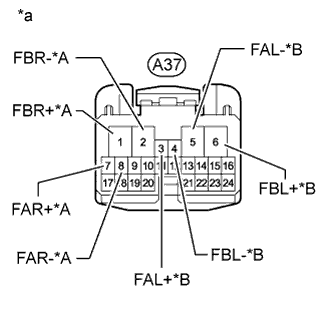
Text in Illustration *A for Front RH *B for Front LH *a Front view of wire harness connector
(to Absorber Control ECU)
-
Check the front absorber control actuator harness and connector.
-
Connect the A42 and/or A17 front absorber control actuator connector.
-
Disconnect the absorber control ECU connector.
-
Measure the resistance according to the value(s) in the table below.
Standard Resistance for Front RH (for DTC C1731) Tester Connection Condition Specified Condition A37-1 (FBR+) - Body ground Always 12.0 to 12.8 Ω A37-2 (FBR-) - Body ground Always 12.0 to 12.8 Ω A37-7 (FAR+) - Body ground Always 12.0 to 12.8 Ω A37-8 (FAR-) - Body ground Always 12.0 to 12.8 Ω for Front LH (for DTC C1732) Tester Connection Condition Specified Condition A37-3 (FAL+) - Body ground Always 12.0 to 12.8 Ω A37-5 (FAL-) - Body ground Always 12.0 to 12.8 Ω A37-6 (FBL+) - Body ground Always 12.0 to 12.8 Ω A37-4 (FBL-) - Body ground Always 12.0 to 12.8 Ω
-
-
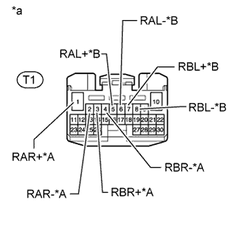
Text in Illustration *A for Rear RH *B for Rear LH *a Front view of wire harness connector
(to Absorber Control ECU)
Check the rear absorber control actuator harness and connector.
-
Connect the T29 and/or U31 rear absorber control actuator connector.
-
Disconnect the absorber control ECU connector.
-
Measure the resistance according to the value(s) in the table below.
Standard Resistance for Rear RH (for DTC C1733) Tester Connection Condition Specified Condition T1-2 (RAR-) - Body ground Always 12.0 to 12.8 Ω T1-3 (RBR+) - Body ground Always 12.0 to 12.8 Ω T1-4 (RBR-) - Body ground Always 12.0 to 12.8 Ω T1-1 (RAR+) - Body ground Always 12.0 to 12.8 Ω for Rear LH (for DTC C1734) Tester Connection Condition Specified Condition T1-5 (RAL+) - Body ground Always 12.0 to 12.8 Ω T1-6 (RAL-) - Body ground Always 12.0 to 12.8 Ω T1-7 (RBL+) - Body ground Always 12.0 to 12.8 Ω T1-8 (RBL-) - Body ground Always 12.0 to 12.8 Ω
-
NG
REPAIR OR REPLACE HARNESS OR CONNECTOR
OK 
REPLACE ABSORBER CONTROL ECU Click here
-