FOUR WHEEL DRIVE CONTROL SYSTEM TC and CG Terminal Circuit
DESCRIPTION
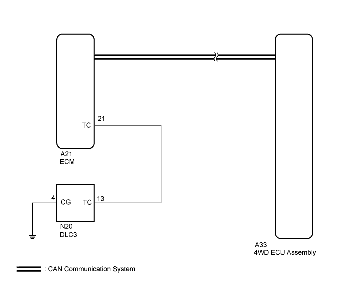
Connecting terminals TC and CG of the DLC3 causes the 4WD ECU assembly to display a DTC on the multi-information display.
WIRING DIAGRAM
INSPECTION PROCEDURE
Tech Tips
Check the condition of each related circuit connector before troubleshooting Click here.
PROCEDURE
-
CHECK CAN COMMUNICATION SYSTEM
-
Check if a CAN communication system DTC is output Click here.
Result Result Proceed to DTC is not output A DTC is output B
B 
GO TO CAN COMMUNICATION SYSTEM (HOW TO PROCEED WITH TROUBLESHOOTING) Click here
A 
-
-
INSPECT DLC3 TERMINAL VOLTAGE (TC TERMINAL VOLTAGE)
-
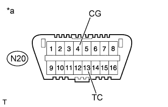
Text in Illustration *a Front view of DLC3 Turn the engine switch on (IG).
-
Measure the voltage according to the value(s) in the table below.
Standard Voltage Tester Connection Switch Condition Specified Condition N20-13 (TC) - N20-4 (CG) Engine switch on (IG) 11 to 14 V -
Turn the engine switch off.
-
Measure the resistance according to the value(s) in the table below.
Standard Resistance Tester Connection Condition Condition N20-4 (CG) - Body ground Always Below 1 Ω
NG 
CHECK HARNESS AND CONNECTOR (ECM - DLC3) Click here
OK
-
-
CHECK HARNESS AND CONNECTOR (ECM - DLC3)
-
Disconnect the A21 ECM connector.
-
Measure the resistance according to the value(s) in the table below.
Standard Resistance Tester Connection Condition Specified Condition A21-21 (TC) - N20-13 (TC) Always Below 1 Ω N20-13 (TC) - Body ground Always 10 kΩ or higher
NG
REPAIR OR REPLACE HARNESS OR CONNECTOR (TC TERMINAL CIRCUIT)
OK 
REPLACE 4WD ECU ASSEMBLY Click here
-
-
CHECK HARNESS AND CONNECTOR (ECM - DLC3)
-
Disconnect the A21 ECM connector.
-
Measure the resistance according to the value(s) in the table below.
Standard Resistance Tester Connection Condition Specified Condition A21-21 (TC) - N20-13 (TC) Always Below 1 Ω N20-13 (TC) - Body ground Always 10 kΩ or higher
NG
REPAIR OR REPLACE HARNESS OR CONNECTOR (TC TERMINAL CIRCUIT)
OK
-
-
CHECK HARNESS AND CONNECTOR (DLC3 CG CIRCUIT)
-
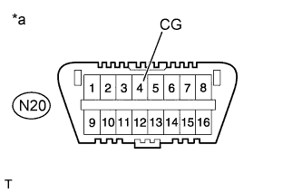
Text in Illustration *a Front view of DLC3 Measure the resistance according to the value(s) in the table below.
Standard Resistance Tester Connection Condition Specified Condition N20-4 (CG) - Body ground Always Below 1 Ω
NG
REPAIR OR REPLACE HARNESS OR CONNECTOR (CG TERMINAL CIRCUIT)
OK
-
-
CHECK WARNING LIGHT (MIL)
-
Text in Illustration *a Front view of DLC3 Using SST, connect terminals TC and CG of the DLC3.
- SST
- 09843-18040
-
Check that the MIL is blinking.
Result Result Proceed to MIL is blinking A MIL is not blinking B
B
REPLACE ECM Click here
A
REPLACE 4WD ECU ASSEMBLY Click here
-