AUTOMATIC TRANSMISSION ASSEMBLY REMOVAL

-
PRECAUTION
Note
After turning the engine switch off, waiting time may be required before disconnecting the cable from the battery terminal. Therefore, make sure to read the disconnecting the cable from the battery terminal notice before proceeding with work Click here.
-
DISCONNECT CABLE FROM NEGATIVE BATTERY TERMINAL
Note
When disconnecting the cable, some systems need to be initialized after the cable is reconnected Click here.
-
REMOVE INTAKE AIR SURGE TANK ASSEMBLY
-
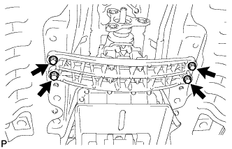
REMOVE FRONT SUSPENSION MEMBER BRACE
-
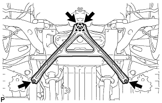
Remove the 4 bolts, and then turn the clip and remove the front suspension member brace.
Tech Tips
Do not remove the clip from the front suspension member brace.
-
-
REMOVE NO. 2 ENGINE UNDER COVER
-
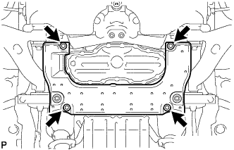
Remove the 4 screws and No. 2 engine under cover.
-
-
DRAIN ENGINE COOLANT
-
DRAIN AUTOMATIC TRANSMISSION FLUID
-
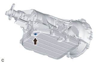
Remove the drain plug and gasket, and drain the ATF.
-
Install a new gasket and the drain plug.
- Torque:
- 20 N*m { 204 kgf*cm, 15 ft.*lbf }
-
-
REMOVE PROPELLER SHAFT WITH CENTER BEARING ASSEMBLY
-
REMOVE NO. 1 EXHAUST PIPE SUPPORT BRACKET SUB-ASSEMBLY
-
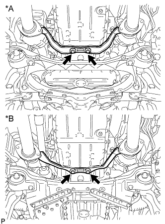
Text in Illustration *A for 2WD *B for AWD Remove the 2 bolts and No. 1 exhaust pipe support bracket.
-
-
REMOVE FRONT CENTER FLOOR BRACE SUB-ASSEMBLY
-
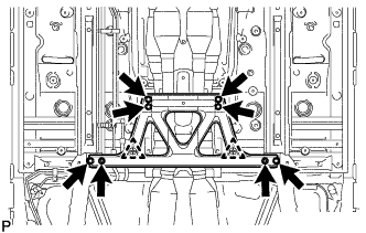
Remove the 6 bolts, 2 nuts, 2 clips and front center floor brace.
-
-
REMOVE STARTER ASSEMBLY
-
REMOVE FLYWHEEL HOUSING SIDE COVER
-
Remove the flywheel housing side cover from the engine assembly.
-
-
REMOVE DRIVE PLATE AND TORQUE CONVERTER SETTING BOLT
-
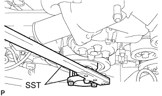
Using SST, hold the crankshaft pulley.
- SST
- 09213-70011 ( 09213-70020 )
- 09330-00021
-
Turn the crankshaft to gain access to each bolt and remove the 6 drive plate and torque converter setting bolts while holding the crankshaft pulley bolt with a wrench.
-
-
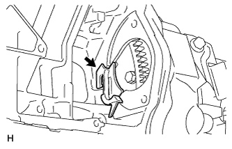
REMOVE FLOOR SHIFT GEAR SHIFTING ROD SUB-ASSEMBLY
-
Move the shift lever to N.
-
Remove the nut, and disconnect the floor shift gear shifting rod sub-assembly.
-
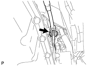
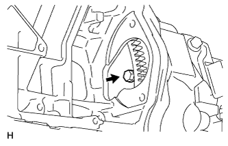
Remove the clip and pin, and disconnect the floor shift gear shifting rod sub-assembly from the transmission control shaft lever RH.
-
-
SUPPORT AUTOMATIC TRANSMISSION ASSEMBLY
-
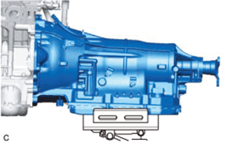
Support the automatic transmission assembly with a transmission jack.
Note
-
In order to protect the automatic transmission oil pan sub-assembly, place attachments on the transmission jack.
-
Make sure that the attachments and the automatic transmission oil pan sub-assembly are centered on the transmission jack.
-
To prevent the automatic transmission oil pan sub-assembly from deforming, do not place any attachments under the automatic transmission oil pan sub-assembly of the automatic transmission assembly.
-
-
-
REMOVE REAR ENGINE MOUNTING MEMBER
-
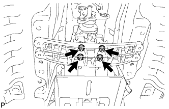
Remove the 4 nuts and disconnect the rear engine mounting member from the automatic transmission assembly.
-
Remove the 4 bolts and separate the rear engine mounting member from the body.
-
-
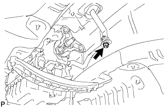
DISCONNECT NO. 2 GROUND WIRE
-
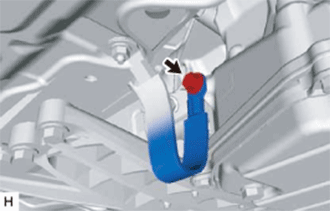
Remove the bolt and disconnect the No. 2 ground wire from the automatic transmission assembly.
-
-
DISCONNECT WIRE HARNESS
-
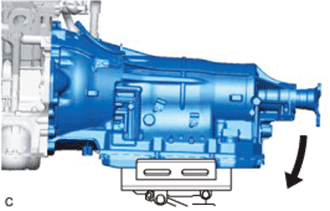
Tilt down the automatic transmission assembly.
Note
Make sure that the cooling fan and fan shroud do not contact the engine assembly when tilting the automatic transmission assembly.
-
Disconnect the park/neutral position switch assembly connector, transmission wire connector and transmission breather hose sub-assembly.
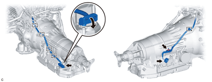
Tech Tips
Detach the claw, press down the lever, and then disconnect the transmission wire connector.
-
Disconnect the 4 clamps and remove the nut and wire harness from the automatic transmission assembly.
-
-
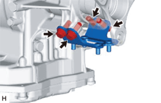
DISCONNECT WATER BY-PASS HOSE (w/ ATF Warmer)
-
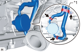
Text in Illustration *1 Hose Clamp Remove the bolt and hose clamp.
-
Slide the 2 clips and disconnect the 2 oil cooler hoses from the transmission oil cooler.
Note
Use a container to catch any coolant which flows out of the 2 water by-pass hoses.
-
-
DISCONNECT OIL COOLER TUBE SUB-ASSEMBLY (w/o ATF Warmer)
-
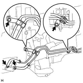
Slide the 2 clips and disconnect the 2 oil cooler hoses from the automatic transmission assembly.
Note
Use a container to catch any ATF which flows out of the 2 oil cooler hoses.
-
Remove the 2 bolts and disconnect the oil cooler tube sub-assembly from the automatic transmission assembly.
-
-
REMOVE AUTOMATIC TRANSMISSION ASSEMBLY
-
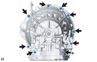
Remove the 9 bolts and automatic transmission assembly.
Note
-
Secure the automatic transmission assembly to the transmission jack using a belt, etc. to prevent it from falling.
-
To prevent damage to the knock pins, do not pry between the automatic transmission assembly and engine assembly.
-
-
-
REMOVE REAR ENGINE MOUNTING INSULATOR
-
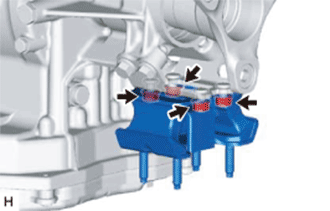
Remove the 4 bolts and rear engine mounting insulator from the rear engine mounting bracket.
-
-
REMOVE REAR ENGINE MOUNTING BRACKET
-
Remove the 4 bolts and rear engine mounting bracket from the automatic transmission assembly.
-
-
REMOVE TORQUE CONVERTER ASSEMBLY
-
Remove the torque converter assembly from the automatic transmission assembly.
Note
Remove the torque converter assembly from the input shaft horizontally.
-
-
INSPECT TORQUE CONVERTER ASSEMBLY
-
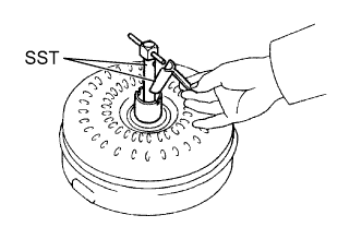
Inspect the one-way clutch.
-
Install SST into the inner race of the one-way clutch.
- SST
- 09350-32014 ( 09351-32010 )
-
Set SST so that it fits in the notch of the torque converter hub and the outer race of the one-way clutch.
- SST
- 09350-32014 ( 09351-32020 )
-
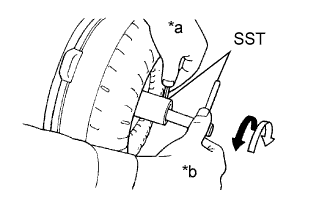
Text in Illustration *a Hold *b Turn 
Difficult 
Smooth With the torque converter assembly standing on its side, check that the clutch locks when SST is turned counterclockwise and rotates freely and smoothly when SST is turned clockwise.
If the results are not as specified, clean the torque converter assembly and recheck the one-way clutch.
If the results still are not as specified even after cleaning the torque converter assembly, replace the torque converter assembly.
-
-
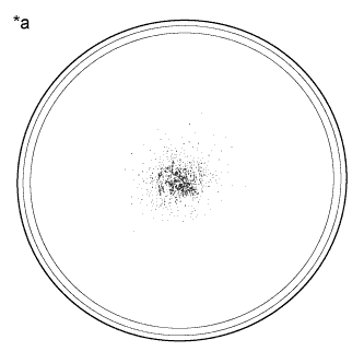
Text in Illustration *a Sample showing maximum allowable amount of powder in ATF Determine the condition of the torque converter assembly.
-
Check that the following conditions are met:
-
During the stall test or when the shift lever is in N, metallic sounds are not emitted from the torque converter assembly.
-
The one-way clutch turns in one direction and locks in the other direction.
-
The amount of powder in the ATF is not more than the sample shown in the illustration.
If the results are not as specified, replace the torque converter assembly.
Tech Tips
The sample illustration shows approximately 0.025 liters (0.026 US qts, 0.022 Imp. qts) of ATF taken from a removed torque converter assembly.
-
-
-
Replace the ATF in the torque converter assembly.
-
If the ATF is discolored and/or has a foul odor, stir the ATF in the torque converter assembly thoroughly and drain the ATF with the torque converter assembly facing upward.
-
-
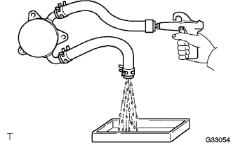
Clean and check the oil cooler and oil pipe line.
-
If the torque converter is inspected or the ATF is replaced, it is necessary to clean the oil cooler and oil pipe line.
Tech Tips
-
Apply compressed air of 196 kPa (2.0 kgf/cm2, 28 psi) into the inlet hose.
-
If a large amount of powder is found in the ATF, add new ATF using a bucket pump and clean the oil cooler and oil pipe line again.
-
-
If the ATF is cloudy, inspect the oil cooler.
-
-
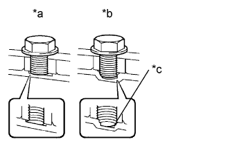
Text in Illustration *a CORRECT *b INCORRECT *c Bottom is damaged Prevent deformation of the torque converter and damage to the oil pump gear.
-
When any marks due to interference are found on the end of a bolt for the torque converter assembly and on the bottom of the bolt hole, replace the bolt and torque converter assembly.
-
Make sure all of the bolts are the same length.
-
Make sure no spring washers are missing.
-
-