VEHICLE STABILITY CONTROL SYSTEM, Diagnostic DTC:C1405, C1406

| DTC Code | DTC Name |
|---|---|
| C1405 | Open or Short in Front Speed Sensor RH Circuit |
| C1406 | Open or Short in Front Speed Sensor LH Circuit |
DESCRIPTION
Refer to DTCs C1401 and C1402 Click here.
| DTC Code | DTC Detection Condition | Trouble Area |
|---|---|---|
| C1405 C1406 |
Either of the following is detected:
|
|
Tech Tips
-
DTC C1405 is for the front speed sensor RH.
-
DTC C1406 is for the front speed sensor LH.
WIRING DIAGRAM
Refer to DTCs C1401 and C1402 Click here.
INSPECTION PROCEDURE
Note
When replacing the brake actuator assembly, perform zero point calibration and store system information Click here.
PROCEDURE
-
CHECK HARNESS AND CONNECTOR (MOMENTARY INTERRUPTION)
-
Using the GTS, check for any momentary interruption in the wire harness and connector corresponding to the DTC Click here.
ABS/VSC/TRC Tester Display Measurement Item/Range Normal Condition Diagnostic Note FR Speed Open Front speed sensor RH open detection / Error or Normal Normal - FL Speed Open Front speed sensor LH open detection / Error or Normal Normal - OK There are no momentary interruptions. Tech Tips
Perform the above inspection before removing the sensor and connector.
Result Result Proceed to OK A NG (for 2WD) B NG (for AWD) C
B 
INSPECT SKID CONTROL SENSOR WIRE Click here
C
CHECK HARNESS AND CONNECTOR (SKID CONTROL ECU - FRONT SPEED SENSOR) Click here
A 
CHECK FOR INTERMITTENT PROBLEMS Click here
-
-
INSPECT SKID CONTROL SENSOR WIRE
-
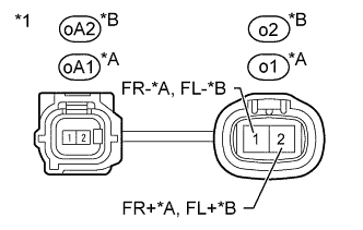
Text in Illustration *A for RH *B for LH *1 Skid Control Sensor Wire Turn the engine switch off.
-
Make sure that there is no looseness at the locking part and the connecting part of the connectors.
-
Remove the skid control sensor wire Click here.
-
Check the connector case and terminals for deformation and corrosion.
Standard condition No deformation or corrosion. -
Measure the resistance according to the value(s) in the table below.
Standard Resistance for RH: Tester Connection Condition Specified Condition oA1-1 - o1-2 (FR+) Always Below 1 Ω oA1-2 - o1-1 (FR-) Always Below 1 Ω oA1-1 - oA1-2 Always 10 kΩ or higher for LH: Tester Connection Condition Specified Condition oA2-1 - o2-2 (FL+) Always Below 1 Ω oA2-2 - o2-1 (FL-) Always Below 1 Ω oA2-1 - oA2-2 Always 10 kΩ or higher Note
Check the speed sensor signal after replacement Click here.
NG 
REPLACE SKID CONTROL SENSOR WIRE Click here
OK 
-
-
CHECK HARNESS AND CONNECTOR (SKID CONTROL ECU - FRONT SPEED SENSOR)
-
Turn the engine switch off.
-
for 2WD:
-
Install the skid control sensor wire Click here.
-
-
Make sure that there is no looseness at the locking part and the connecting part of the connectors.
-
Disconnect the A13 skid control ECU (brake actuator assembly) connector.
-
for 2WD:
-
Disconnect the o1 and/or o2 speed sensor connector.
-
-
for AWD:
-
Disconnect the A72 and/or A71 speed sensor connector.
-
-
Check the connector case and terminals for deformation and corrosion.
Standard condition No deformation or corrosion. -
Measure the resistance according to the value(s) in the table below.
Standard Resistance for RH (2WD): Tester Connection Condition Specified Condition A13-7 (FR+) - o1-2 (FR+) Always Below 1 Ω A13-7 (FR+) - Body ground Always 10 kΩ or higher A13-6 (FR-) - o1-1 (FR-) Always Below 1 Ω A13-6 (FR-) - Body ground Always 10 kΩ or higher for LH (2WD): Tester Connection Condition Specified Condition A13-19 (FL+) - o2-2 (FL+) Always Below 1 Ω A13-19 (FL+) - Body ground Always 10 kΩ or higher A13-18 (FL-) - o2-1 (FL-) Always Below 1 Ω A13-18 (FL-) - Body ground Always 10 kΩ or higher for RH (AWD): Tester Connection Condition Specified Condition A13-7 (FR+) - A72-1 (FR+) Always Below 1 Ω A13-7 (FR+) - Body ground Always 10 kΩ or higher A13-6 (FR-) - A72-2 (FR-) Always Below 1 Ω A13-6 (FR-) - Body ground Always 10 kΩ or higher for LH (AWD): Tester Connection Condition Specified Condition A13-19 (FL+) - A71-1 (FL+) Always Below 1 Ω A13-19 (FL+) - Body ground Always 10 kΩ or higher A13-18 (FL-) - A71-2 (FL-) Always Below 1 Ω A13-18 (FL-) - Body ground Always 10 kΩ or higher Note
Check the speed sensor signal after replacement Click here.
NG
REPAIR OR REPLACE HARNESS OR CONNECTOR
OK
-
-
INSPECT SKID CONTROL ECU (SENSOR INPUT)
-
Reconnect the skid control ECU (brake actuator assembly) connector.
-
Text in Illustration *A for RH *B for LH *a Front view of wire harness connector
(to Front Speed Sensor)
for 2WD:
-
Disconnect the speed sensor connector.
-
Measure the voltage according to the value(s) in the table below.
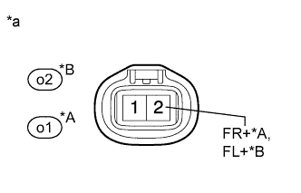
Standard Voltage for RH: Tester Connection Switch Condition Specified Condition o1-2 (FR+) - Body ground Engine switch on (IG) 8 to 14 V for LH: Tester Connection Switch Condition Specified Condition o2-2 (FL+) - Body ground Engine switch on (IG) 8 to 14 V
-
-
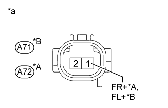
Text in Illustration *A for RH *B for LH *a Front view of wire harness connector
(to Front Speed Sensor)
for AWD:
-
Disconnect the speed sensor connector.
-
Measure the voltage according to the value(s) in the table below.
Standard Voltage for RH: Tester Connection Switch Condition Specified Condition A72-1 (FR+) - Body ground Engine switch on (IG) 8 to 14 V for LH: Tester Connection Switch Condition Specified Condition A71-1 (FL+) - Body ground Engine switch on (IG) 8 to 14 V
Note
Check the speed sensor signal after replacement Click here.
-
NG
REPLACE BRAKE ACTUATOR ASSEMBLY Click here
OK
-
-
RECONFIRM DTC
-
Clear the DTCs Click here.
-
Turn the engine switch off.
-
Start the engine.
-
Perform a road test.
-
Check if the same DTC is recorded Click here.
Result Result Proceed to DTCs (C1405 and C1406) are not output A DTCs (C1405 and/or C1406) are output (for 2WD) B DTCs (C1405 and/or C1406) are output (for AWD) C Tech Tips
If troubleshooting has been carried out according to Problem Symptoms Table, refer back to the table and proceed to the next step Click here.
B
REPLACE FRONT AXLE HUB SUB-ASSEMBLY Click here
C
REPLACE FRONT SPEED SENSOR Click here
A
CHECK FOR INTERMITTENT PROBLEMS Click here
-