VEHICLE STABILITY CONTROL SYSTEM, Diagnostic DTC:C1241

| DTC Code | DTC Name |
|---|---|
| C1241 | Low Power Supply Voltage Malfunction |
DESCRIPTION
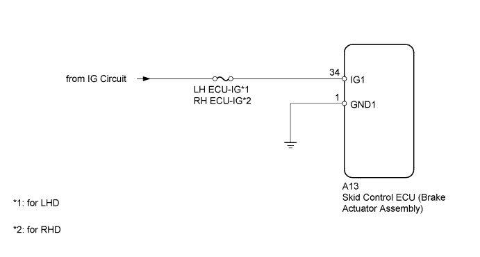
If a malfunction is detected in the power supply circuit, the skid control ECU (housed in the brake actuator assembly) stores this DTC and the fail-safe function prohibits ABS operation.
This DTC is stored when the IG1 terminal voltage deviates from the DTC detection condition due to a malfunction in the power supply or charging circuit, such as the battery or generator circuit, etc.
The DTC is cleared when the IG1 terminal voltage returns to normal.
| DTC Code | DTC Detection Condition | Trouble Area |
|---|---|---|
| C1241 | One of the following conditions is met:
|
|
WIRING DIAGRAM
INSPECTION PROCEDURE
Note
-
When replacing the brake actuator assembly, perform zero point calibration and store system information Click here.
-
Inspect the fuses for circuits related to this system before performing the following inspection procedure.
PROCEDURE
-
INSPECT BATTERY
-
Inspect the battery voltage.
Standard voltage 11 to 14 V Result Result Proceed to OK A NG (for 2GR-FSE) B NG (for 4GR-FSE) C
B 
CHECK OR REPLACE CHARGING SYSTEM OR BATTERY Click here
C
CHECK OR REPLACE CHARGING SYSTEM OR BATTERY Click here
A 
-
-
CHECK HARNESS AND CONNECTOR (IG1 TERMINAL)
-
Disconnect the skid control ECU (brake actuator assembly) connector.
-
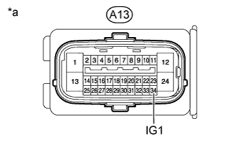
Text in Illustration *a Front view of wire harness connector
(to Skid Control ECU [Brake Actuator Assembly])
Measure the voltage according to the value(s) in the table below.
Standard Voltage Tester Connection Switch Condition Specified Condition A13-34 (IG1) - Body ground Engine switch on (IG) 11 to 14 V Result Result Proceed to OK A NG (for 2GR-FSE) B NG (for 4GR-FSE) C
NG
REPAIR OR REPLACE HARNESS OR CONNECTOR
OK
-
-
CHECK HARNESS AND CONNECTOR (GND1 TERMINAL)
-
Disconnect the skid control ECU (brake actuator assembly) connector.
-
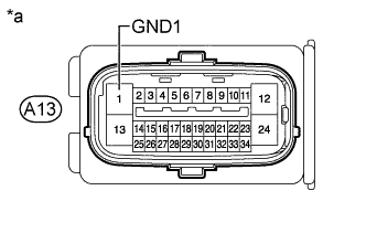
Text in Illustration *a Front view of wire harness connector
(to Skid Control ECU [Brake Actuator Assembly])
Measure the resistance according to the value(s) in the table below.
Standard Resistance Tester Connection Condition Specified Condition A13-1 (GND1) - Body ground Always Below 1 Ω
NG
REPAIR OR REPLACE HARNESS OR CONNECTOR
OK
-
-
RECONFIRM DTC
-
Clear the DTCs Click here.
-
Turn the engine switch off.
-
Start the engine.
-
Perform a road test.
-
Check if the same DTC is output Click here.
Result Result Proceed to DTC is not output A DTC is output B
B
REPLACE BRAKE ACTUATOR ASSEMBLY Click here
A 
CHECK FOR INTERMITTENT PROBLEMS Click here
-