LIGHTING SYSTEM Inside Handle Illumination Light Circuit
DESCRIPTION
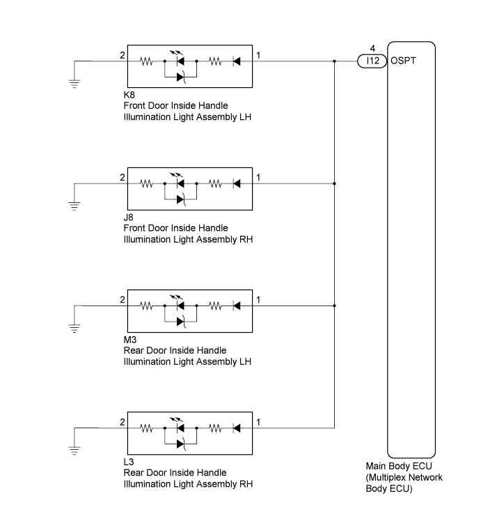
The main body ECU (multiplex network ECU) controls the inside handle illumination lights.
WIRING DIAGRAM
INSPECTION PROCEDURE
PROCEDURE
-
PERFORM ACTIVE TEST USING INTELLIGENT TESTER
-
Connect the intelligent tester to the DLC3.
-
Turn the ignition switch to ON.
-
Turn the intelligent tester on.
-
Enter the following menus: Body / Main Body / Active Test.
-
Check that the inside handle illumination lights come on.
Main Body Tester Display Test Part Control Range Diagnostic Note Inside Handle Illumination Inside handle illumination lights ON/OFF Ignition switch is turned off just before performing the Active Test. OK Inside handle illumination lights come on.
NG 
CHECK HARNESS AND CONNECTOR (INSIDE HANDLE ILLUMINATION LIGHT ASSEMBLY - MAIN BODY ECU (MULTIPLEX NETWORK BODY ECU)) Click here
OK 
PROCEED TO NEXT SUSPECTED AREA SHOWN IN PROBLEM SYMPTOMS TABLE Click here
-
-
CHECK HARNESS AND CONNECTOR (INSIDE HANDLE ILLUMINATION LIGHT ASSEMBLY - MAIN BODY ECU (MULTIPLEX NETWORK BODY ECU))
-
Disconnect the I12 main body ECU (multiplex network body ECU) connector.
-
Disconnect the K8 front door inside handle illumination light assembly LH connector.
-
Disconnect the J8 front door inside handle illumination light assembly RH connector.
-
Disconnect the M3 rear door inside handle illumination light assembly LH connector.
-
Disconnect the L3 rear door inside handle illumination light assembly RH connector.
-
Measure the resistance according to the value(s) in the table below.
Standard Resistance Tester Connection Condition Specified Condition I12-4 (OSPT) - K8-1 Always Below 1 Ω I12-4 (OSPT) - J8-1 Always Below 1 Ω I12-4 (OSPT) - M3-1 Always Below 1 Ω I12-4 (OSPT) - L3-1 Always Below 1 Ω I12-4 (OSPT) - Body ground Always 10 kΩ or higher
NG 
REPAIR OR REPLACE HARNESS OR CONNECTOR
OK
REPLACE MAIN BODY ECU (MULTIPLEX NETWORK BODY ECU) Click here
-