CAN COMMUNICATION SYSTEM, Diagnostic DTC:U1002, U1115

| DTC Code | DTC Name |
|---|---|
| U1002 | Lost Communication with Gateway Module (Main Body ECU) |
| U1115 | Lost Communication with Tilt and Telescopic Module |
DESCRIPTION
-
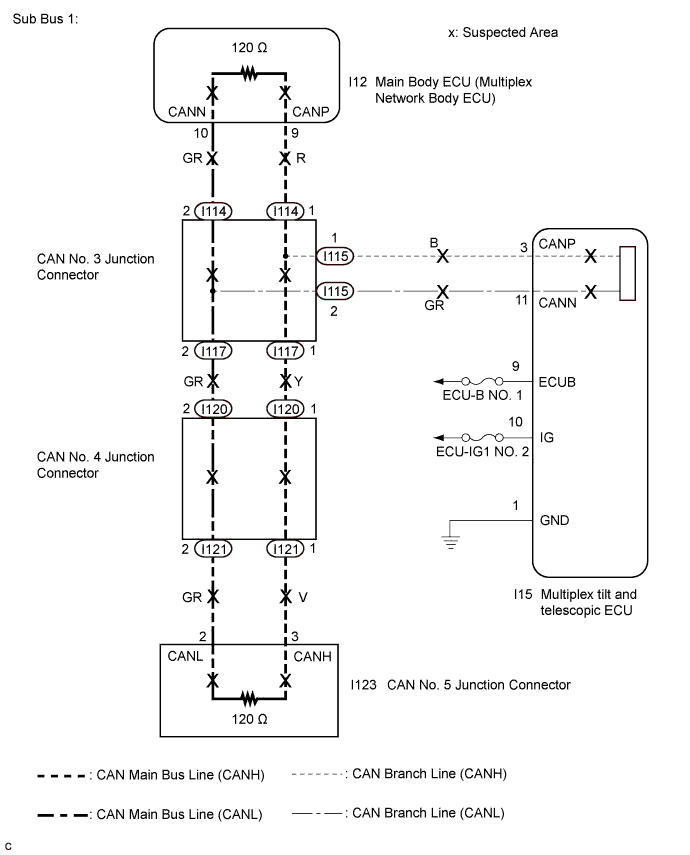
The main body ECU will store this DTC when no signals can be received from the ECUs that have been memorized as those that are connected to sub bus 1.
-
When the main body ECU receives a response signal from the ECUs connected to sub bus 1, the main body ECU recognizes and memorizes that the ECU is connected to sub bus 1. Based on this memorized data, the main body ECU monitors for malfunctions in the ECUs connected to sub bus 1 when communicating with those ECUs. If the main body ECU cannot receive response signals from the ECUs that have been memorized as those connected to sub bus 1, the main body ECU determines that a malfunction exists.
| DTC No. | DTC Detection Condition | Trouble Area |
|---|---|---|
| U1002 | Main body ECU cannot receive signals from all ECUs that have been memorized as those connected to sub bus 1. |
|
| U1115 | No communication from the multiplex tilt and telescopic ECU |
|
Tech Tips
This diagnosis procedure is for when DTC U1002 is output by the main body ECU (Intelligent tester display: Main Body).
WIRING DIAGRAM
INSPECTION PROCEDURE
Note
-
Before measuring the resistance of the CAN bus, turn the ignition switch off and leave the vehicle for 1 minute or more without operating the key, switches or opening or closing the doors. After that, disconnect the cable from the negative (-) battery terminal and leave the vehicle for 1 minute or more before measuring the resistance.
-
After turning the ignition switch off, waiting time may be required before disconnecting the cable from the negative (-) battery terminal. Therefore, make sure to read the disconnecting the cable from the negative (-) battery terminal notices before proceeding with work Click here.
-
Because the order of diagnosis is important to allow correct diagnosis, make sure to begin troubleshooting using How to Proceed with Troubleshooting when CAN communication system related DTCs are output Click here.
-
After performing repairs, perform the DTC check procedure and confirm that the DTCs are not output again.
-
DTC check procedure: Turn the ignition switch to ON and wait at least 10 seconds.
-
After the repair, perform Communication Bus Check and check that all the ECUs and sensors connected to the CAN communication system are displayed Click here.
Tech Tips
-
Operating the ignition switch, any other switches or a door triggers related ECU and sensor communication on the CAN. This communication will cause the resistance value to change.
-
Even after DTCs are cleared, if a DTC is stored again after driving the vehicle for a while, the malfunction may be occurring due to vibration of the vehicle. In such a case, wiggling the ECUs or wire harness while performing the inspection below may help determine the cause of the malfunction.
-
Connectors that connect to the CAN junction connector can be distinguished by color of their CAN bus lines. When the connectors have been disconnected from the CAN junction connector, reconnecting the connectors to non-original positions on the CAN junction connector does not affect system performance. However, it is preferred to reconnect the connectors to their original positions to avoid negative effects on the wiring such as tension on the wiring harnesses, and to make future maintenance easier.
PROCEDURE
-
CHECK SUB BUS 1
-
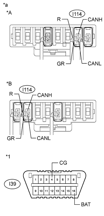
Text in Illustration *A for TMC Made *B for TMMR Made *1 DLC3 *a Component with harness connected
(CAN No. 3 Junction Connector)
Disconnect the cable from the negative (-) battery terminal.
-
Measure the resistance according to the value(s) in the table below.
Standard Resistance Tester Connection Condition Specified Condition Result I114-1 (CANH) - I114-2 (CANL) Cable disconnected from negative (-) battery terminal 54 to 69 Ω Below 54 Ω:
Short circuit between bus lines
70 Ω or higher:
Open circuit in a main bus line
I114-1 (CANH) - I39-4 (CG) Cable disconnected from negative (-) battery terminal 200 Ω or higher Below 200 Ω:
CANH ground short
I114-2 (CANL) - I39-4 (CG) Cable disconnected from negative (-) battery terminal 200 Ω or higher Below 200 Ω:
CANL ground short
I114-1 (CANH) - I39-16 (BAT) Cable disconnected from negative (-) battery terminal 6 kΩ or higher Below 6 kΩ:
CANH +B short
I114-2 (CANL) - I39-16 (BAT) Cable disconnected from negative (-) battery terminal 6 kΩ or higher Below 6 kΩ:
CANL +B short
Result Result Proceed to OK A Open circuit in CAN main bus line B Short circuit between bus lines C
-
Ground short
-
+B short
D -
B 
CHECK FOR OPEN IN SUB BUS 1 MAIN LINES (MAIN BODY ECU (MULTIPLEX NETWORK BODY ECU)) Click here
C
CHECK FOR SHORT IN SUB BUS 1 LINES (MAIN BODY ECU (MULTIPLEX NETWORK BODY ECU)) Click here
D
CHECK FOR SHORT IN SUB BUS 1 LINE (CAN NO. 3 J/C) Click here
A 
-
-
CHECK FOR OPEN IN SUB BUS 1 LINES (MULTIPLEX TILT AND TELESCOPIC ECU)
-
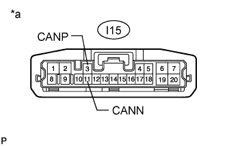
Text in Illustration *a Front view of wire harness connector
(to Multiplex Tilt and Telescopic ECU)
Disconnect the connector from the multiplex tilt and telescopic ECU.
-
Measure the resistance according to the value(s) in the table below.
Standard Resistance Tester Connection Condition Specified Condition I15-3 (CANP) - I15-11 (CANN) Cable disconnected from negative (-) battery terminal 54 to 69 Ω
NG 
REPAIR OR REPLACE CAN BRANCH LINE OR CONNECTOR (MULTIPLEX TILT AND TELESCOPIC ECU - CAN NO. 3 J/C)
OK
-
-
CHECK FOR POWER SOURCE CIRCUIT (MULTIPLEX TILT AND TELESCOPIC ECU)
-
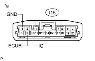
Text in Illustration *a Front view of wire harness connector
(to Multiplex Tilt and Telescopic ECU)
Measure the resistance according to the value(s) in the table below.
Standard Resistance Tester Connection Condition Specified Condition I15-1 (GND) - Body ground Cable disconnected from negative (-) battery terminal Below 1 Ω -
Reconnect the cable to the negative (-) battery terminal.
-
Measure the voltage according to the value(s) in the table below.
Standard Voltage Tester Connection Switch Condition Specified Condition I15-9 (ECUB) - Body ground Always 11 to 14 V I15-10 (IG) - Body ground Ignition switch ON 11 to 14 V
NG
REPAIR OR REPLACE POWER SOURCE CIRCUIT (MULTIPLEX TILT AND TELESCOPIC ECU)
OK
-
-
CHECK DTC OUTPUT
-
Reconnect the connector to the multiplex tilt and telescopic ECU.
-
Connect the intelligent tester to the DLC3.
-
Turn the ignition switch to ON.
-
Turn the intelligent tester on.
-
Clear the DTCs.
-
Turn the ignition switch off.
-
Turn the ignition switch to ON and recheck for DTCs.
Result Result Proceed to U1002 is not output A U1002 is output B
B
REPLACE MAIN BODY ECU (MULTIPLEX NETWORK BODY ECU) Click here
A 
SYMPTOM SIMULATION Click here
-
-
REPLACE MAIN BODY ECU (MULTIPLEX NETWORK BODY ECU)
-
Replace the main body ECU (multiplex network body ECU) Click here.
NEXT
-
-
CHECK DTC OUTPUT
-
Connect the intelligent tester to the DLC3.
-
Turn the ignition switch to ON and recheck for DTCs.
Result Result Proceed to U1002 is not output A U1002 is output B
B
REPLACE MULTIPLEX TILT AND TELESCOPIC ECU Click here
A
END
-
-
CHECK FOR OPEN IN SUB BUS 1 MAIN LINES (MAIN BODY ECU (MULTIPLEX NETWORK BODY ECU))
-

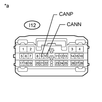
Text in Illustration *a Front view of wire harness connector
(to Main Body ECU (Multiplex Network Body ECU))
Disconnect the main body ECU (multiplex network body ECU) connector.
-
Measure the resistance according to the value(s) in the table below.
Standard Resistance Tester Connection Condition Specified Condition I12-9 (CANP) - I12-10 (CANN) Cable disconnected from negative (-) battery terminal 108 to 132 Ω
NG
CHECK FOR OPEN IN SUB BUS 1 LINES (CAN NO. 3 J/C) Click here
OK
REPLACE MAIN BODY ECU (MULTIPLEX NETWORK BODY ECU) Click here
-
-
CHECK FOR OPEN IN SUB BUS 1 LINES (CAN NO. 3 J/C)
-
Reconnect the main body ECU (multiplex network body ECU) connector.
-
Disconnect the wire harness connectors (I114 and I117) from the CAN No. 3 junction connector.
-
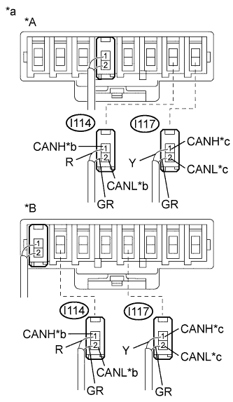
Text in Illustration *A for TMC Made *B for TMMR Made *a Rear view of wire harness connector
(to CAN No. 3 Junction Connector)
*b to Main Body ECU (Multiplex Network Body ECU) *c to CAN No. 4 Junction Connector Measure the resistance according to the value(s) in the table below.
Standard Resistance Tester Connection Condition Specified Condition I114-1 (CANH) - I114-2 (CANL) Cable disconnected from negative (-) battery terminal 108 to 132 Ω I117-1 (CANH) - I117-2 (CANL) Cable disconnected from negative (-) battery terminal 108 to 132 Ω Result Result Proceed to OK A NG (to Main body ECU (multiplex network body ECU) main bus line) B NG (to CAN No. 4 junction connector main bus line) C Note
-
Before disconnecting the connectors, make a note of where they are connected.
-
Reconnect each connector to its original position.
-
B
REPAIR OR REPLACE CAN MAIN BUS LINE OR CONNECTOR (CAN NO. 3 J/C - MAIN BODY ECU (MULTIPLEX NETWORK BODY ECU))
C
CHECK FOR OPEN IN SUB BUS 1 LINES (CAN NO. 4 J/C) Click here
A
REPLACE CAN NO. 3 JUNCTION CONNECTOR
-
-
CHECK FOR OPEN IN SUB BUS 1 LINES (CAN NO. 4 J/C)
-
Reconnect the wire harness connectors (I114 and I117) to the CAN No. 3 junction connector.
-
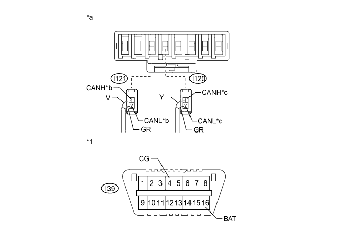
Disconnect the wire harness connectors (I120 and I121) from the CAN No. 4 junction connector.
-
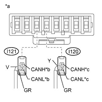
Text in Illustration *a Rear view of wire harness connector
(to CAN No. 4 Junction Connector)
*b to CAN No. 5 Junction Connector *c to CAN No. 3 Junction Connector Measure the resistance according to the value(s) in the table below.
Standard Resistance Tester Connection Condition Specified Condition I120-1 (CANH) - I120-2 (CANL) Cable disconnected from negative (-) battery terminal 108 to 132 Ω I121-1 (CANH) - I121-2 (CANL) Cable disconnected from negative (-) battery terminal 108 to 132 Ω Result Result Proceed to OK A NG (to CAN No. 3 junction connector main bus line) B NG (to CAN No. 5 junction connector main bus line) C Note
-
Before disconnecting the connectors, make a note of where they are connected.
-
Reconnect each connector to its original position.
-
B
REPAIR OR REPLACE CAN MAIN BUS LINE OR CONNECTOR (CAN NO. 3 J/C - CAN NO. 4 J/C)
C
CHECK FOR OPEN IN SUB BUS 1 LINES (CAN NO. 5 J/C) Click here
A
REPLACE CAN NO. 4 JUNCTION CONNECTOR
-
-
CHECK FOR OPEN IN SUB BUS 1 LINES (CAN NO. 5 J/C)
-
Reconnect the wire harness connectors (I120 and I121) to the CAN No. 4 junction connector.
-
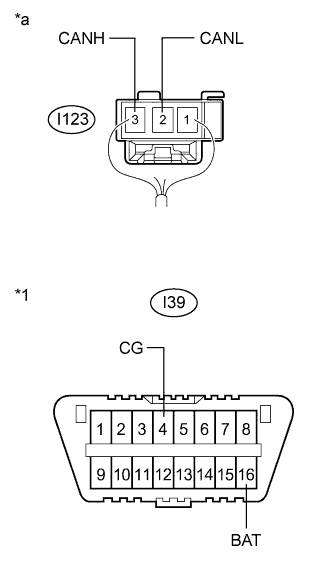
Disconnect the instrument panel wire connector from the CAN No. 5 junction connector.
-
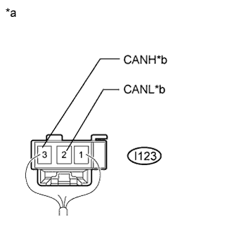
Text in Illustration *a Rear view of wire harness connector
(to CAN No. 5 Junction Connector)
*b to CAN No. 4 Junction Connector Measure the resistance according to the value(s) in the table below.
Standard Resistance Tester Connection Condition Specified Condition I123-3 (CANH) - I123-2 (CANL) Cable disconnected from negative (-) battery terminal 108 to 132 Ω
NG
REPAIR OR REPLACE CAN MAIN BUS LINE OR CONNECTOR (CAN NO. 4 J/C - CAN NO. 5 J/C)
OK
REPLACE CAN NO. 5 JUNCTION CONNECTOR
-
-
CHECK FOR SHORT IN SUB BUS 1 LINES (MAIN BODY ECU (MULTIPLEX NETWORK BODY ECU))
-
Text in Illustration *a Front view of wire harness connector
(to Main Body ECU (Multiplex Network Body ECU))
Disconnect the main body ECU (multiplex network body ECU) connector.
-
Measure the resistance according to the value(s) in the table below.
Standard Resistance Tester Connection Condition Specified Condition I12-9 (CANP) - I12-10 (CANN) Cable disconnected from negative (-) battery terminal 108 to 132 Ω
NG
CHECK FOR SHORT IN SUB BUS 1 LINES (CAN NO. 3 J/C) Click here
OK
REPLACE MAIN BODY ECU (MULTIPLEX NETWORK BODY ECU) Click here
-
-
CHECK FOR SHORT IN SUB BUS 1 LINES (CAN NO. 3 J/C)
-
Reconnect the main body ECU (multiplex network body ECU) connector.
-
Disconnect the wire harness connectors (I114, I115 and I117) from the CAN No. 3 junction connector.
-
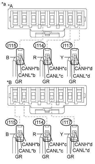
Text in Illustration *A for TMC Made *B for TMMR Made *a Rear view of wire harness connector
(to CAN No. 3 Junction Connector)
*b to Multiplex Tilt and Telescopic ECU *c to Main Body ECU (Multiplex Network Body ECU) *d to CAN No. 4 Junction Connector Measure the resistance according to the value(s) in the table below.
Standard Resistance Tester Connection Condition Specified Condition I114-1 (CANH) - I114-2 (CANL) Cable disconnected from negative (-) battery terminal 108 to 132 Ω I115-1 (CANH) - I115-2 (CANL) Cable disconnected from negative (-) battery terminal 200 Ω or higher I117-1 (CANH) - I117-2 (CANL) Cable disconnected from negative (-) battery terminal 108 to 132 Ω Result Result Proceed to OK A NG (to Main body ECU (multiplex network body ECU) main bus line) B NG (to CAN No. 4 junction connector main bus line) C NG (to Multiplex tilt and telescopic ECU) D Note
-
Before disconnecting the connectors, make a note of where they are connected.
-
Reconnect each connector to its original position.
-
B
REPAIR OR REPLACE CAN MAIN BUS LINE OR CONNECTOR (CAN NO. 3 J/C - MAIN BODY ECU (MULTIPLEX NETWORK BODY ECU))
C
CHECK FOR SHORT IN SUB BUS 1 LINES (CAN NO. 4 J/C) Click here
D
CHECK FOR SHORT IN SUB BUS 1 LINES (MULTIPLEX TILT AND TELESCOPIC ECU) Click here
A
REPLACE CAN NO. 3 JUNCTION CONNECTOR
-
-
CHECK FOR SHORT IN SUB BUS 1 LINES (CAN NO. 4 J/C)
-
Disconnect the wire harness connectors (I120 and I121) from the CAN No. 4 junction connector.
-
Text in Illustration *a Rear view of wire harness connector
(to CAN No. 4 Junction Connector)
*b to CAN No. 5 Junction Connector *c to CAN No. 3 Junction Connector Measure the resistance according to the value(s) in the table below.
Standard Resistance Tester Connection Condition Specified Condition I120-1 (CANH) - I120-2 (CANL) Cable disconnected from negative (-) battery terminal 1 MΩ or higher I121-1 (CANH) - I121-2 (CANL) Cable disconnected from negative (-) battery terminal 108 to 132 Ω Result Result Proceed to OK A NG (to CAN No. 3 junction connector main bus line) B NG (to CAN No. 5 junction connector main bus line) C Note
-
Before disconnecting the connectors, make a note of where they are connected.
-
Reconnect each connector to its original position.
-
B
REPAIR OR REPLACE CAN MAIN BUS LINE OR CONNECTOR (CAN NO. 3 J/C - CAN NO. 4 J/C)
C
CHECK FOR SHORT IN SUB BUS 1 LINES (CAN NO. 5 J/C) Click here
A
REPLACE CAN NO. 4 JUNCTION CONNECTOR
-
-
CHECK FOR SHORT IN SUB BUS 1 LINES (CAN NO. 5 J/C)
-
Disconnect the wire harness connector from the CAN No. 5 junction connector.
-
Text in Illustration *a Rear view of wire harness connector
(to CAN No. 5 Junction Connector)
*b to CAN No. 4 Junction Connector Measure the resistance according to the value(s) in the table below.
Standard Resistance Tester Connection Condition Specified Condition I123-3 (CANH) - I123-2 (CANL) Cable disconnected from negative (-) battery terminal 1 MΩ or higher
NG
REPAIR OR REPLACE CAN MAIN BUS LINE OR CONNECTOR (CAN NO. 4 J/C - CAN NO. 5 J/C)
OK
REPLACE CAN NO. 5 JUNCTION CONNECTOR
-
-
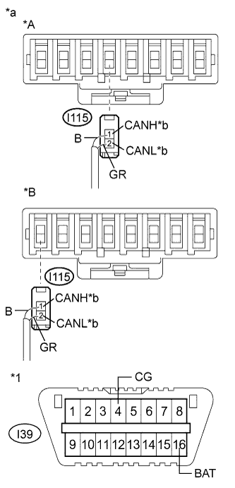
CHECK FOR SHORT IN SUB BUS 1 LINES (MULTIPLEX TILT AND TELESCOPIC ECU)
-
Disconnect the connector from the multiplex tilt and telescopic ECU.
-
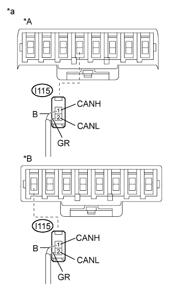
Text in Illustration *A for TMC Made *B for TMMR Made *a Rear view of harness connected
(to CAN No. 3 Junction Connector)
*b to Multiplex Tilt and Telescopic ECU Measure the resistance according to the value(s) in the table below.
Standard Resistance Tester Connection Condition Specified Condition I115-1 (CANH) - I115-2 (CANL) Cable disconnected from negative (-) battery terminal 1 MΩ or higher Note
-
Before disconnecting the connector, make a note of where it is connected.
-
Reconnect the connector to its original position.
-
NG
REPAIR OR REPLACE CAN BRANCH LINE OR CONNECTOR (CAN NO. 3 J/C - MULTIPLEX TILT AND TELESCOPIC ECU)
OK
REPLACE MULTIPLEX TILT AND TELESCOPIC ECU Click here
-
-
CHECK FOR SHORT IN SUB BUS 1 LINE (CAN NO. 3 J/C)
-
Disconnect the wire harness connectors (I114, I115 and I117) from the CAN No. 3 junction connector.
-
Measure the resistance according to the value(s) in the table below.
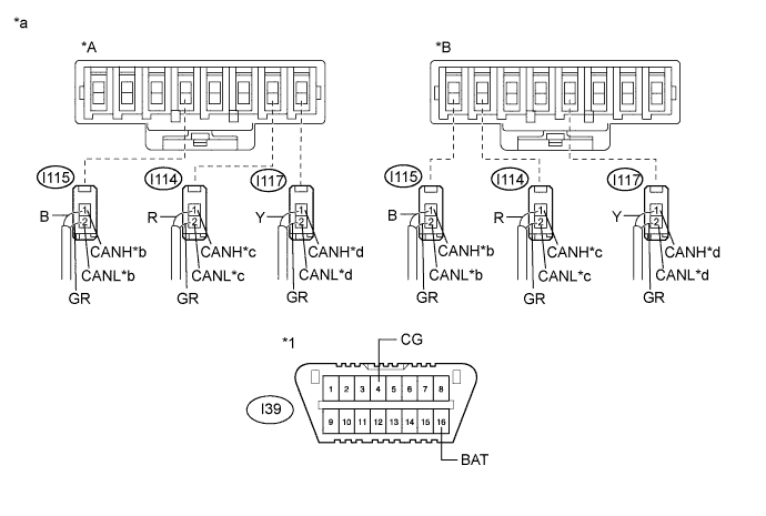
Standard Resistance Tester Connection Condition Specified Condition Purpose Connected to I114-1 (CANH) - I39-4 (CG) Cable disconnected from negative (-) battery terminal 200 Ω or higher Inspection for CANH ground short Main body ECU (multiplex network body ECU) I114-2 (CANL) - I39-4 (CG) Cable disconnected from negative (-) battery terminal 200 Ω or higher Inspection for CANL ground short I117-1 (CANH) - I39-4 (CG) Cable disconnected from negative (-) battery terminal 200 Ω or higher Inspection for CANH ground short CAN No. 4 junction connector I117-2 (CANL) - I39-4 (CG) Cable disconnected from negative (-) battery terminal 200 Ω or higher Inspection for CANL ground short I115-1 (CANH) - I39-4 (CG) Cable disconnected from negative (-) battery terminal 200 Ω or higher Inspection for CANH ground short Multiplex tilt and telescopic ECU I115-2 (CANL) - I39-4 (CG) Cable disconnected from negative (-) battery terminal 200 Ω or higher Inspection for CANL ground short I114-1 (CANH) - I39-16 (BAT) Cable disconnected from negative (-) battery terminal 6 kΩ or higher Inspection for CANH +B short Main body ECU (multiplex network body ECU) I114-2 (CANL) - I39-16 (BAT) Cable disconnected from negative (-) battery terminal 6 kΩ or higher Inspection for CANL +B short I117-1 (CANH) - I39-16 (BAT) Cable disconnected from negative (-) battery terminal 6 kΩ or higher Inspection for CANH +B short CAN No. 4 junction connector I117-2 (CANL) - I39-16 (BAT) Cable disconnected from negative (-) battery terminal 6 kΩ or higher Inspection for CANL +B short I115-1 (CANH) - I39-16 (BAT) Cable disconnected from negative (-) battery terminal 6 kΩ or higher Inspection for CANH +B short Multiplex tilt and telescopic ECU I115-2 (CANL) - I39-16 (BAT) Cable disconnected from negative (-) battery terminal 6 kΩ or higher Inspection for CANL +B short Text in Illustration *A for TMC Made *B for TMMR Made *1 DLC3 - - *a Rear view of wire harness connector
(to CAN No. 3 Junction Connector)
*b to Multiplex Tilt and Telescopic ECU *c to Main Body ECU (Multiplex Network Body ECU) *d to CAN No. 4 Junction Connector Result Result Proceed to OK A NG (to Main body ECU (multiplex network body ECU) main bus line) B NG (to CAN No. 4 junction connector main bus line) C NG (to Multiplex tilt and telescopic ECU) D Note
-
Before disconnecting the connectors, make a note of where they are connected.
-
Reconnect each connector to its original position.
Tech Tips
It is only necessary to perform the inspection in the above table for the result (short circuit) that was obtained in the Check Sub Bus 1 inspection.
Find the necessary inspection from the Purpose column that matches the result in the Result column from the Check Sub Bus 1 inspection.
-
B
CHECK FOR SHORT IN SUB BUS 1 LINE (MAIN BODY ECU (MULTIPLEX NETWORK BODY ECU)) Click here
C
CHECK FOR SHORT IN SUB BUS 1 LINE (CAN NO. 4 J/C) Click here
D
CHECK FOR SHORT IN SUB BUS 1 LINE (MULTIPLEX TILT AND TELESCOPIC ECU) Click here
A
REPLACE CAN NO. 3 JUNCTION CONNECTOR
-
-
CHECK FOR SHORT IN SUB BUS 1 LINE (MAIN BODY ECU (MULTIPLEX NETWORK BODY ECU))
-
Disconnect the main body ECU (multiplex network body ECU) connector.
-
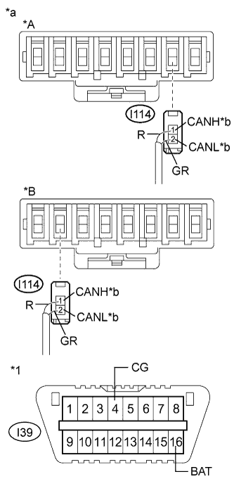
Text in Illustration *A for TMC Made *B for TMMR Made *1 DLC3 *a Rear view of wire harness connector
(to CAN No. 3 Junction Connector)
*b to Main Body ECU (Multiplex Network Body ECU) Measure the resistance according to the value(s) in the table below.
Standard Resistance Tester Connection Condition Specified Condition Purpose I114-1 (CANH) - I39-4 (CG) Cable disconnected from negative (-) battery terminal 200 Ω or higher Below 200 Ω:
CANH ground short
I114-2 (CANL) - I39-4 (CG) Cable disconnected from negative (-) battery terminal 200 Ω or higher Below 200 Ω:
CANL ground short
I114-1 (CANH) - I39-16 (BAT) Cable disconnected from negative (-) battery terminal 6 kΩ or higher Below 6 kΩ:
CANH +B short
I114-2 (CANL) - I39-16 (BAT) Cable disconnected from negative (-) battery terminal 6 kΩ or higher Below 6 kΩ:
CANL +B short
Note
-
Before disconnecting the connector, make a note of where it is connected.
-
Reconnect the connector to its original position.
Tech Tips
It is only necessary to perform the inspection in the above table for the result (short circuit) that was obtained in the Check Sub Bus 1 inspection.
Find the necessary inspection from the Purpose column that matches the result in the Result column from the Check Sub Bus 1 inspection.
-
NG
REPAIR OR REPLACE CAN MAIN BUS LINE OR CONNECTOR (CAN NO. 3 J/C - MAIN BODY ECU (MULTIPLEX NETWORK BODY ECU))
OK
REPLACE MAIN BODY ECU (MULTIPLEX NETWORK BODY ECU) Click here
-
-
CHECK FOR SHORT IN SUB BUS 1 LINE (CAN NO. 4 J/C)
-
Disconnect the wire harness connectors (I120 and I121) from the CAN No. 4 junction connector.
-
Measure the resistance according to the value(s) in the table below.
Standard Resistance Tester Connection Condition Specified Condition Purpose Connected to I120-1 (CANH) - I39-4 (CG) Cable disconnected from negative (-) battery terminal 200 Ω or higher Inspection for CANH ground short CAN No. 3 junction connector I120-2 (CANL) - I39-4 (CG) Cable disconnected from negative (-) battery terminal 200 Ω or higher Inspection for CANL ground short I121-1 (CANH) - I39-4 (CG) Cable disconnected from negative (-) battery terminal 200 Ω or higher Inspection for CANH ground short CAN No. 5 junction connector I121-2 (CANL) - I39-4 (CG) Cable disconnected from negative (-) battery terminal 200 Ω or higher Inspection for CANL ground short I120-1 (CANH) - I39-16 (BAT) Cable disconnected from negative (-) battery terminal 6 kΩ or higher Inspection for CANH +B short CAN No. 3 junction connector I120-2 (CANL) - I39-16 (BAT) Cable disconnected from negative (-) battery terminal 6 kΩ or higher Inspection for CANL +B short I121-1 (CANH) - I39-16 (BAT) Cable disconnected from negative (-) battery terminal 6 kΩ or higher Inspection for CANH +B short CAN No. 5 junction connector I121-2 (CANL) - I39-16 (BAT) Cable disconnected from negative (-) battery terminal 6 kΩ or higher Inspection for CANL +B short Text in Illustration *1 DLC3 - - *a Rear view of wire harness connector
(to CAN No. 4 Junction Connector)
*b to CAN No. 5 Junction Connector *c to CAN No. 3 Junction Connector - - Result Result Proceed to OK A NG (to CAN No. 3 junction connector main bus line) B NG (to CAN No. 5 junction connector main bus line) C Note
-
Before disconnecting the connectors, make a note of where they are connected.
-
Reconnect each connector to its original position.
Tech Tips
It is only necessary to perform the inspection in the above table for the result (short circuit) that was obtained in the Check Sub Bus 1 inspection.
-
B
REPAIR OR REPLACE CAN MAIN BUS LINE OR CONNECTOR (CAN NO. 3 J/C - CAN NO. 4 J/C)
C
CHECK FOR SHORT IN SUB BUS 1 LINE (CAN NO. 5 J/C) Click here
A
REPLACE CAN NO. 4 JUNCTION CONNECTOR
-
-
CHECK FOR SHORT IN SUB BUS 1 LINE (CAN NO. 5 J/C)
-
Disconnect the wire harness connector from the CAN No. 5 junction connector.
-
Text in Illustration *1 DLC3 *a Rear view of wire harness connector
(to CAN No. 5 Junction Connector)
Measure the resistance according to the value(s) in the table below.
Standard Resistance Tester Connection Condition Specified Condition Purpose I123-3 (CANH) - I39-4 (CG) Cable disconnected from negative (-) battery terminal 200 Ω or higher Below 200 Ω:
CANH ground short
I123-2 (CANL) - I39-4 (CG) Cable disconnected from negative (-) battery terminal 200 Ω or higher Below 200 Ω:
CANL ground short
I123-3 (CANH) - I39-16 (BAT) Cable disconnected from negative (-) battery terminal 6 kΩ or higher Below 6 kΩ:
CANH +B short
I123-2 (CANL) - I39-16 (BAT) Cable disconnected from negative (-) battery terminal 6 kΩ or higher Below 6 kΩ:
CANL +B short
Tech Tips
It is only necessary to perform the inspection in the above table for the result (short circuit) that was obtained in the Check Sub Bus 1 inspection.
Find the necessary inspection from the Purpose column that matches the result in the Result column from the Check Sub Bus 1 inspection.
NG
REPAIR OR REPLACE CAN MAIN BUS LINE OR CONNECTOR (CAN NO. 4 J/C - CAN NO. 5 J/C)
OK
REPLACE CAN NO. 5 JUNCTION CONNECTOR
-
-
CHECK FOR SHORT IN SUB BUS 1 LINE (MULTIPLEX TILT AND TELESCOPIC ECU)
-
Disconnect the connector from the multiplex tilt and telescopic ECU.
-
Text in Illustration *A for TMC Made *B for TMMR Made *1 DLC3 *a Rear view of wire harness connector
(to CAN No. 3 Junction Connector)
*b to Multiplex Tilt and Telescopic ECU Measure the resistance according to the value(s) in the table below.
Standard Resistance Tester Connection Condition Specified Condition Purpose I115-1 (CANH) - I39-4 (CG) Cable disconnected from negative (-) battery terminal 200 Ω or higher Below 200 Ω:
CANH ground short
I115-2 (CANL) - I39-4 (CG) Cable disconnected from negative (-) battery terminal 200 Ω or higher Below 200 Ω:
CANL ground short
I115-1 (CANH) - I39-16 (BAT) Cable disconnected from negative (-) battery terminal 6 kΩ or higher Below 6 kΩ:
CANH +B short
I115-2 (CANL) - I39-16 (BAT) Cable disconnected from negative (-) battery terminal 6 kΩ or higher Below 6 kΩ:
CANL +B short
Note
-
Before disconnecting the connector, make a note of where it is connected.
-
Reconnect the connector to its original position.
Tech Tips
-
It is only necessary to perform the inspection in the above table for the result (short circuit) that was obtained in the Check Sub Bus 1 inspection.
-
If the resistance becomes abnormal when an ECU connector is reconnected, there may be a short in the ECU.
Find the necessary inspection from the Purpose column that matches the result in the Result column from the Check Sub Bus 1 inspection.
-
NG
REPAIR OR REPLACE CAN BRANCH LINE OR CONNECTOR (CAN NO. 3 J/C - MULTIPLEX TILT AND TELESCOPIC ECU)
OK
REPLACE MULTIPLEX TILT AND TELESCOPIC ECU Click here
-