AIR CONDITIONING SYSTEM(for Automatic Air Conditioning System), Diagnostic DTC:B1412/12
| DTC Code | DTC Name |
|---|---|
| B1412/12 | Ambient Temperature Sensor Circuit |
DESCRIPTION
The thermistor assembly (ambient temperature sensor) is installed in the front part of the cooler condenser assembly to detect the ambient temperature and control the air conditioning auto mode. The sensor connected to the air conditioning amplifier assembly detects fluctuations in the ambient temperature. This data is used for controlling the room temperature. The sensor sends a signal to the air conditioning amplifier assembly. The resistance of the thermistor assembly (ambient temperature sensor) changes in accordance with the cooler thermistor temperature (ambient temperature). As the temperature decreases, the resistance increases. As the temperature increases, the resistance decreases.
The air conditioning amplifier assembly applies a voltage (5 V) to the thermistor assembly (ambient temperature sensor) and reads voltage changes as changes in the resistance of the thermistor assembly (ambient temperature sensor).
The combination meter assembly sends these signals to the air conditioning amplifier assembly.*1
| DTC No. | DTC Detection Condition | Trouble Area |
|---|---|---|
| B1412/12 | An open or short in the thermistor assembly (ambient temperature sensor) circuit. |
|
*1 : w/ Rear Fog Light
*2 : w/o Rear Fog Light
WIRING DIAGRAM
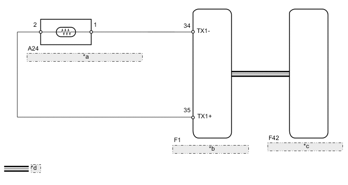
| *a | THERMISTOR ASSEMBLY (AMBIENT TEMPERATURE SENSOR) |
| *b | COMBINATION METER ASSEMBLY |
| *c | AIR CONDITIONING AMPLIFIER ASSEMBLY |
| *d | CAN Communication Line |
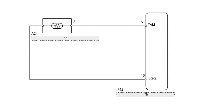
| *a | THERMISTOR ASSEMBLY (AMBIENT TEMPERATURE SENSOR) |
| *b | AIR CONDITIONING AMPLIFIER ASSEMBLY |
PROCEDURE
-
READ VALUE USING INTELLIGENT TESTER (AMBIENT TEMPERATURE SENSOR)
-
Connect the intelligent tester to the DLC3.
-
Turn the ignition switch to ON.
-
Turn the intelligent tester on.
-
Enter the following menus: Body / Air Conditioner / Data List.
-
According to the display on the intelligent tester, read the Data List.
Air Conditioner Tester Display Measurement Item/Range Normal Condition Diagnostic Note Ambient Temp Sensor Thermistor assembly (ambient temperature sensor) /
Min: -23.3°C (-9.94°F)
Max: 65.95°C (150.71°F)
Actual ambient temperature displayed Open in the circuit: -23.3°C (-9.94°F)
Short in the circuit: 65.95°C (150.71°F)
OK The display is as specified in the normal condition column. Result Result Proceed to OK (When troubleshooting according to the DTC) A OK (When troubleshooting according to problem symptoms table) B NG C
B 
PROCEED TO NEXT SUSPECTED AREA SHOWN IN PROBLEM SYMPTOMS TABLE Click here
C 
INSPECT THERMISTOR ASSEMBLY (AMBIENT TEMPERATURE SENSOR) Click here
A 
-
-
CHECK FOR DTC
-
Clear the DTCs Click here.
-
Check for DTCs Click here.
OK DTC B1412 is not output Result Result Proceed to OK A NG (w/ Rear Fog Light) B NG (w/o Rear Fog Light) C
A
END
B
REPLACE COMBINATION METER ASSEMBLY Click here
C
REPLACE AIR CONDITIONING AMPLIFIER ASSEMBLY Click here
-
-
INSPECT THERMISTOR ASSEMBLY (AMBIENT TEMPERATURE SENSOR)
-
Remove the thermistor assembly (ambient temperature sensor Click here.
-
Inspect the thermistor assembly (ambient temperature sensor Click here.
Result Result Proceed to OK (w/o Rear Fog Light) A OK (w/ Rear Fog Light) B NG C
B
CHECK HARNESS AND CONNECTOR (AMBIENT TEMPERATURE SENSOR - COMBINATION METER ASSEMBLY) Click here
C
REPLACE THERMISTOR ASSEMBLY (AMBIENT TEMPERATURE SENSOR) Click here
A
-
-
CHECK HARNESS AND CONNECTOR (AMBIENT TEMPERATURE SENSOR - AIR CONDITIONING AMPLIFIER)
-
Disconnect the A24 thermistor assembly (ambient temperature sensor) connector.
-
Disconnect the F42 air conditioning amplifier assembly connector.
-
Measure the resistance according to the value(s) in the table below.
Standard Resistance (Check for Open) Tester Connection Condition Specified Condition A24-2 - F42-5 (TAM) Always Below 1 Ω A24-1 - F42-13 (SG-2) Always Below 1 Ω Standard Resistance (Check for Short) Tester Connection Condition Specified Condition A24-1 - Body ground Always 10 kΩ or higher A24-2 - Body ground Always 10 kΩ or higher
OK
REPLACE AIR CONDITIONING AMPLIFIER ASSEMBLY Click here
NG
REPAIR OR REPLACE HARNESS OR CONNECTOR
-
-
CHECK HARNESS AND CONNECTOR (AMBIENT TEMPERATURE SENSOR - COMBINATION METER ASSEMBLY)
-
Disconnect the A24 thermistor assembly (ambient temperature sensor) connector.
-
Disconnect the F1 combination meter assembly connector.
-
Measure the resistance according to the value(s) in the table below.
Standard Resistance (Check for Open) Tester Connection Condition Specified Condition A24-2 - F1-35 (TX1+) Always Below 1 Ω A24-1 - F1-34 (TX1-) Always Below 1 Ω Standard Resistance (Check for Short) Tester Connection Condition Specified Condition A24-1 - Body ground Always 10 kΩ or higher A24-2 - Body ground Always 10 kΩ or higher
OK
REPLACE COMBINATION METER ASSEMBLY Click here
NG
REPAIR OR REPLACE HARNESS OR CONNECTOR
-