METER / GAUGE SYSTEM, Diagnostic DTC:B1507, B1508
| DTC Code | DTC Name |
|---|---|
| B1507 | Open in Turn Signal Circuit |
| B1508 | Short in Turn Signal / Hazard Flasher Circuit |
DESCRIPTION
The combination meter assembly receives headlight dimmer switch information signals, and flash the turn signal lights.
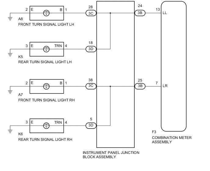
WIRING DIAGRAM
CAUTION / NOTICE / HINT
Note
Inspect the fuses and bulbs for circuits related to this system before performing the following inspection procedure.
PROCEDURE
-
INSPECT LIGHTS
-
Inspect each turn signal light illumination.
Result Result Proceed to One side of the turn signal lights does not illuminate. A Front turn signal lights do not illuminate. B Rear turn signal lights do not illuminate. C
B 
CHECK HARNESS AND CONNECTOR (FRONT TURN SIGNAL LIGHT - INSTRUMENT PANEL JUNCTION BLOCK) Click here
C
CHECK HARNESS AND CONNECTOR (REAR TURN SIGNAL LIGHT - INSTRUMENT PANEL JUNCTION BLOCK) Click here
A 
-
-
CHECK HARNESS AND CONNECTOR (COMBINATION METER - INSTRUMENT PANEL JUNCTION BLOCK)
-
Disconnect the F3 combination meter assembly connector.
-
Disconnect the 3B instrument panel junction block assembly connector.
-
Measure the resistance according to the value(s) in the table below.
Standard Resistance (Check for Open) for LH Tester Connection Condition Specified Condition F3-13 (LL) - 3B-24 Always Below 1 Ω for RH Tester Connection Condition Specified Condition F3-7 (LR) - 3B-25 Always Below 1 Ω Standard Resistance (Check for Short) for LH Tester Connection Condition Specified Condition F3-13 (LL) - Body ground Always 10 kΩ or higher for RH Tester Connection Condition Specified Condition F3-7 (LR) - Body ground Always 10 kΩ or higher Result Result Proceed to NG A OK B
A 
REPAIR OR REPLACE HARNESS OR CONNECTOR
B
INSPECT INSTRUMENT PANEL JUNCTION BLOCK ASSEMBLY Click here
-
-
CHECK HARNESS AND CONNECTOR (FRONT TURN SIGNAL LIGHT - INSTRUMENT PANEL JUNCTION BLOCK)
-
Disconnect the A7*1 or A8*2 front turn signal light connector.
-
*1: for RH
-
*2: for LH
-
-
Disconnect the 3C instrument panel junction block assembly connector.
-
Measure the resistance according to the value(s) in the table below.
Standard Resistance (Check for Open) for LH Tester Connection Condition Specified Condition A8-1 (B) - 3C-28 Always Below 1 Ω A8-2 (E) - Body ground Always Below 1 Ω for RH Tester Connection Condition Specified Condition A7-1 (B) - 3C-38 Always Below 1 Ω A7-2 (E) - Body ground Always Below 1 Ω Standard Resistance (Check for Short) for LH Tester Connection Condition Specified Condition A8-1 (B) -Body ground Always 10 kΩ or higher for RH Tester Connection Condition Specified Condition A7-1 (B) -Body ground Always 10 kΩ or higher Result Result Proceed to NG A OK B
A
REPAIR OR REPLACE HARNESS OR CONNECTOR
B
INSPECT INSTRUMENT PANEL JUNCTION BLOCK ASSEMBLY Click here
-
-
CHECK HARNESS AND CONNECTOR (REAR TURN SIGNAL LIGHT - INSTRUMENT PANEL JUNCTION BLOCK)
-
Disconnect the K6*1 or K5*2 rear turn signal light connector.
-
*1: for RH
-
*2: for LH
-
-
Disconnect the 3D instrument panel junction block assembly connector.
-
Measure the resistance according to the value(s) in the table below.
Standard Resistance (Check for Open) for LH Tester Connection Condition Specified Condition K5-4 (TRN) - 3D-18 Always Below 1 Ω K5-3 (E) -Body ground Always Below 1 Ω for RH Tester Connection Condition Specified Condition K6-4 (TRN) - 3D-5 Always Below 1 Ω K6-3 (E) -Body ground Always Below 1 Ω Standard Resistance (Check for Short) for LH Tester Connection Condition Specified Condition K5-4 (TRN) -Body ground Always 10 kΩ or higher for RH Tester Connection Condition Specified Condition K6-4 (TRN) -Body ground Always 10 kΩ or higher Result Result Proceed to NG A OK B
A
REPAIR OR REPLACE HARNESS OR CONNECTOR
B
-
-
INSPECT INSTRUMENT PANEL JUNCTION BLOCK ASSEMBLY
-
Remove the instrument panel junction block assembly Click here.
-
Remove the main body ECU (multiplex network body ECU).
-
Measure the resistance according to the value(s) in the table below.
Standard Resistance Tester Connection Condition Specified Condition 3B-25 - 3C-38 Always Below 1 Ω 3B-25 - 3D-5 Always Below 1 Ω 3B-24 - 3C-28 Always Below 1 Ω 3B-24 - 3C-18 Always Below 1 Ω
OK
REPLACE COMBINATION METER ASSEMBLY Click here
NG
REPLACE INSTRUMENT PANEL JUNCTION BLOCK ASSEMBLY Click here
-