METER / GAUGE SYSTEM, Diagnostic DTC:B1500
| DTC Code | DTC Name |
|---|---|
| B1500 | Fuel Sender Open Detected |
DESCRIPTION
This DTC is stored when the combination meter detects the fuel sender gauge malfunction.
| DTC No. | DTC Detection Condition | Trouble Area |
|---|---|---|
| B1500 | When combination meter detects fuel sender gauge malfunction |
|
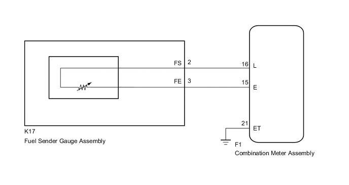
WIRING DIAGRAM
PROCEDURE
-
PERFORM ACTIVE TEST USING GTS (FUEL METER OPERATION)
-
Connect the GTS to the DLC3.
-
Turn the ignition switch to ON.
-
Turn the GTS on.
-
Enter the following menus: Body Electrical / Combination Meter / Active Test.
-
Check the operation by referring to the table below.
Combination Meter Item Test part Control Range Diagnostic Note Fuel Meter Operation Fuel gauge Sender E, Empty, Warning 1/4, 1/2, 3/4, Full, Sender F - OK Fuel receiver gauge indication is normal.
NG 
REPLACE COMBINATION METER ASSEMBLY Click here
OK 
-
-
READ VALUE USING GTS (FUEL INPUT)
-
Connect the GTS to the DLC3.
-
Turn the ignition switch to ON.
-
Turn the GTS on.
-
Enter the following menus: Body Electrical / Combination Meter / Data List.
-
Check the values by referring to the table below.
Combination Meter Item Measurement Item/Range Normal Condition Diagnostic Note Fuel Input Fuel sender gauge input
Min.: 0
Max.: 127.5
Fuel sender input value Unit: Liter Result Result Proceed to Fuel level data can be displayed on the GTS and DTC B1500 is output. A Fuel level data cannot be displayed on the GTS. B
A
REPLACE COMBINATION METER ASSEMBLY Click here
B
-
-
INSPECT FUEL SENDER GAUGE ASSEMBLY
-
Remove the fuel sender gauge assembly.
-
for 1NR-FE: Click here
-
for 1NZ-FE: Click here
-
for 1ND-TV: Click here
-
-
Inspect the fuel sender gauge assembly.
-
for 1NR-FE: Click here
-
for 1NZ-FE: Click here
-
for 1ND-TV: Click here
Result Result Proceed to OK A NG (for 1NR-FE) B NG (for 1NZ-FE) C NG (for 1ND-TV) D -
B
REPLACE FUEL SENDER GAUGE ASSEMBLY Click here
C
REPLACE FUEL SENDER GAUGE ASSEMBLY Click here
D
REPLACE FUEL SENDER GAUGE ASSEMBLY Click here
A
-
-
CHECK HARNESS AND CONNECTOR (COMBINATION METER ASSEMBLY - FUEL SENDER GAUGE ASSEMBLY)
-
Disconnect the F1 combination meter assembly connector.
-
Disconnect the K17 fuel sender gauge assembly connector.
-
Measure the resistance according to the value(s) in the table below.
Standard Resistance (Check for Open) Tester Connector Condition Specified Condition F1-15(E) - K17-3(FE) Always Below 1 Ω F1-16(L) - K17-2(FS) Always Below 1 Ω F1-21(ET) - Body ground Always Below 1 Ω Standard Resistance (Check for Short) Tester Connector Condition Specified Condition F1-16(L) - Body ground Always 10 kΩ or higher F1-15(E) - Body ground Always 10 kΩ or higher
OK
REPLACE COMBINATION METER ASSEMBLY Click here
NG
REPAIR OR REPLACE HARNESS OR CONNECTOR
-