KEY REMINDER WARNING SYSTEM(w/o Entry and Start System) Key Reminder Buzzer does not Sound
DESCRIPTION
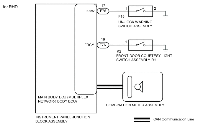
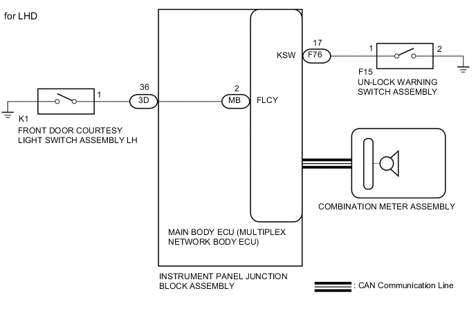
The key reminder warning buzzer sounds when the driver side door is opened while the ignition switch is in the LOCK or ACC positions. The key reminder warning buzzer is activated when the main body ECU (multiplex network body ECU) sends a key switch signal and driver side courtesy light switch signal to the combination meter.
WIRING DIAGRAM
CAUTION / NOTICE / HINT
Tech Tips
Since the key reminder warning system has functions that use CAN communication, first confirm that there is no malfunction in the communication system by inspecting the CAN communication functions in accordance with How to Proceed with Troubleshooting. Then conduct the following troubleshooting procedure.
PROCEDURE
-
CHECK FRONT DOOR COURTESY LIGHT SWITCH
-
Open the driver door and check that the open door indicator on the combination meter comes on.
OK Open door indicator comes on.
NG 
GO TO DOOR COURTESY LIGHT SWITCH CIRCUIT Click here
OK 
-
-
READ VALUE USING INTELLIGENT TESTER (KEY UNLOCK WARNING SW)
-
Connect the intelligent tester to the DLC3.
-
Turn the ignition switch to ON.
-
Turn the intelligent tester on.
-
Enter the following menus: Body Electrical / Main Body / Data List/
-
According to the display on the intelligent tester, read the Data List.
Main Body Tester Display Measurement Item/Range Normal Condition Diagnostic Note Key Unlock warning SW Unlock warning switch signal / ON or OFF ON: Key is in ignition key cylinder
OFF: No key is in ignition key cylinder
- OK When the unlock warning switch is operated, the display changes as shown in the table.
NG 
INSPECT UN-LOCK WARNING SWITCH ASSEMBLY Click here
OK
-
-
CHECK COMBINATION METER ASSEMBLY (BUZZER OPERATION)
-
Remove the key from the key cylinder, turn the light control switch on the headlight dimmer switch assembly to the tail position, and open the driver door.
OK The light reminder warning buzzer sounds. Tech Tips
The key reminder warning system sounds the buzzer built in to the combination meter for key reminder warnings. This buzzer is also used for the light reminder warning system. Therefore, check the operation of the combination meter buzzer by checking if the buzzer sounds to inform that the lights are still on.
OK
REPLACE MAIN BODY ECU (MULTIPLEX NETWORK BODY ECU) Click here
NG
REPLACE COMBINATION METER ASSEMBLY Click here
-
-
INSPECT UN-LOCK WARNING SWITCH ASSEMBLY
-
Remove the unlock warning switch Click here.
-
Inspect the unlock warning switch Click here.
NG
REPLACE UN-LOCK WARNING SWITCH ASSEMBLY Click here
OK
-
-
CHECK HARNESS AND CONNECTOR (UNLOCK WARNING SWITCH - MAIN BODY ECU)
-
Disconnect the F15 unlock warning switch and F76 main body ECU (multiplex network body ECU) connectors.
-
Measure the resistance according to the value(s) in the table below.
Standard Resistance Tester Connection Condition Specified Condition F15-1 - F76-17 (KSW) Always Below 1 Ω F15-2 - Body ground Below 1 Ω F15-1 - Body ground 10 kΩ or higher
NG
REPLACE HARNESS OR CONNECTOR
OK
-
-
REPLACE MAIN BODY ECU (MULTIPLEX NETWORK BODY ECU)
-
Temporarily replace the main body ECU (multiplex network body ECU) with a new or normally functioning one Click here.
NEXT
-
-
READ VALUE USING INTELLIGENT TESTER (KEY UNLOCK WARNING SW)
-
Connect the intelligent tester to the DLC3.
-
Turn the ignition switch to ON.
-
Turn the intelligent tester on.
-
Enter the following menus: Body Electrical / Main Body / Data List/
-
According to the display on the intelligent tester, read the Data List.
Main Body Tester Display Measurement Item/Range Normal Condition Diagnostic Note Key Unlock warning SW Unlock warning switch signal / ON or OFF ON: Key is in ignition key cylinder
OFF: No key is in ignition key cylinder
- OK When the unlock warning switch is operated, the display changes as shown in the table.
OK
END (MAIN BODY ECU (MULTIPLEX NETWORK BODY ECU) IS DEFECTIVE)
NG
REPLACE INSTRUMENT PANEL JUNCTION BLOCK ASSEMBLY
-