VEHICLE STABILITY CONTROL SYSTEM, Diagnostic DTC:C1241
| DTC Code | DTC Name |
|---|---|
| C1241 | Low Power Supply Voltage Malfunction |
DESCRIPTION
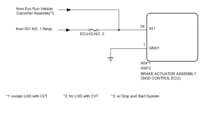
If a malfunction is detected in the power supply circuit, the brake actuator assembly (skid control ECU) stores this DTC and the fail-safe function prohibits ABS operation.
This DTC is stored when the IG1 terminal voltage deviates from the DTC detection condition due to a malfunction in the power supply or charging circuit such as the battery or generator circuit, etc.
The DTC is cancelled when the IG1 terminal voltage returns to normal.
| DTC NO. | DTC Detection Condition | Trouble Area |
|---|---|---|
| C1241 | When any of the following is detected:
|
|
WIRING DIAGRAM
CAUTION / NOTICE / HINT
Note
-
When replacing the brake actuator assembly (skid control ECU), perform zero point calibration Click here.
-
Inspect the fuses for circuits related to this system before performing the following inspection procedure.
PROCEDURE
-
INSPECT BATTERY
-
Check the battery voltage.
Standard voltage 11 to 14 V Result Result Proceed to OK A NG (for 1ND-TV) B NG (for 1NR-FE) C
B 
CHECK OR REPLACE CHARGING SYSTEM OR BATTERY Click here
C
CHECK OR REPLACE CHARGING SYSTEM OR BATTERY Click here
A 
-
-
CHECK TERMINAL VOLTAGE (IG1)
-
Disconnect the A54 or A56 brake actuator assembly (skid control ECU) connector.
-
Turn the ignition switch to ON.
-
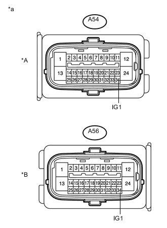
Text in Illustration *A except LHD with CVT *B for LHD with CVT *a Front view of wire harness connector
(to Brake actuator assembly (Skid control ECU))
Measure the voltage according to the value(s) in the table below.
Standard Voltage except LHD with CVT Tester Connection Switch Condition Specified Condition A54-34 (IG1) - Body ground Ignition switch ON 11 to 14 V for LHD with CVT Tester Connection Switch Condition Specified Condition A56-34 (IG1) - Body ground Ignition switch ON 11 to 14 V -
Reconnect the A54 or A56 brake actuator assembly (skid control ECU) connector.
Result Result Proceed to OK A NG (w/o Stop and Start System) B NG (w/ Stop and Start System) C
B
REPAIR OR REPLACE HARNESS OR CONNECTOR (IG1 CIRCUIT)
C
GO TO STOP AND START SYSTEM Click here
A
-
-
CHECK HARNESS AND CONNECTOR (GND1)
-
Turn the ignition switch off.
-
Disconnect the A54 or A56 brake actuator assembly (skid control ECU) connector.
-
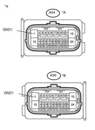
Text in Illustration *A except LHD with CVT *B for LHD with CVT *a Front view of wire harness connector
(to Brake actuator assembly (Skid control ECU))
Measure the resistance according to the value(s) in the table below.
Standard Resistance except LHD with CVT Tester Connection Condition Specified Condition A54-1 (GND1) - Body ground Always Below 1 Ω for LHD with CVT Tester Connection Condition Specified Condition A56-1 (GND1) - Body ground Always Below 1 Ω -
Reconnect the A54 or A56 brake actuator assembly (skid control ECU) connector.
NG
REPAIR OR REPLACE HARNESS OR CONNECTOR (GND CIRCUIT)
OK
-
-
RECONFIRM DTC
-
Clear the DTC Click here.
-
Start the engine.
-
Drive the vehicle at a speed of 20 km/h (12 mph) or more for 30 seconds or more.
-
Check if the same DTC is recorded Click here.
Result Result Proceed to DTC is not output A DTC is output (for LHD) B DTC is output (for RHD) C Tech Tips
If troubleshooting has been carried out according to the Problem Symptoms Table, refer back to the table and proceed to the next step Click here.
A
CHECK FOR INTERMITTENT PROBLEMS (SYMPTOM SIMULATION) Click here
B
REPLACE BRAKE ACTUATOR ASSEMBLY (SKID CONTROL ECU) Click here
C
REPLACE BRAKE ACTUATOR ASSEMBLY (SKID CONTROL ECU) Click here
-