VEHICLE STABILITY CONTROL SYSTEM, Diagnostic DTC:C1421, C1281, C1423, C1424
| DTC Code | DTC Name |
|---|---|
| C1421 | Open or Short in Master Cylinder Pressure Sensor |
| C1281 | Master Cylinder Pressure Sensor Output Malfunction (Test Mode DTC) |
| C1423 | Master Cylinder Pressure Sensor Zero Point Low Malfunction |
| C1424 | Master Cylinder Pressure Sensor Output Malfunction |
DESCRIPTION
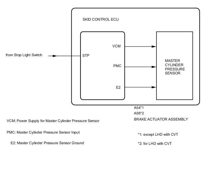
The master cylinder pressure sensor is connected to the skid control ECU.
| DTC NO. | DTC Detection Condition | Trouble Area |
|---|---|---|
| C1421 | Either of the following is detected:
|
Brake actuator assembly (Master cylinder pressure sensor) |
| C1281 | Detected only during Test Mode. | Brake actuator assembly (Master cylinder pressure sensor) |
| C1423 | The PMC terminal voltage is less than 0.27 V for 5 seconds or more. | Brake actuator assembly (Master cylinder pressure sensor) |
| C1424 | Any of the following is detected:
|
Brake actuator assembly (Master cylinder pressure sensor) |
WIRING DIAGRAM
Refer to DTC C1425 Click here.
CAUTION / NOTICE / HINT
Note
-
When replacing the brake actuator assembly (skid control ECU), perform zero point calibration Click here.
-
Inspect the fuses for circuits related to this system before performing the following inspection procedure.
PROCEDURE
-
REPLACE BRAKE ACTUATOR ASSEMBLY (SKID CONTROL ECU)
-
Replace the brake actuator assembly (master cylinder pressure sensor).
NEXT 
END
-