VEHICLE STABILITY CONTROL SYSTEM, Diagnostic DTC:C1428
| DTC Code | DTC Name |
|---|---|
| C1428 | Motor Circuit Malfunction |
DESCRIPTION
| DTC NO. | DTC Detection Condition | Trouble Area |
|---|---|---|
| C1428 | With the ABS motor relay OFF and the ABS motor fail safe relay ON, an open in the motor circuit continues for 2 seconds or more. | Brake actuator assembly (Motor circuit) |
WIRING DIAGRAM
Refer to DTCs C146C, C146D and C1361 Click here.
CAUTION / NOTICE / HINT
Note
-
When replacing the brake actuator assembly (skid control ECU), perform zero point calibration Click here.
-
Inspect the fuses for circuits related to this system before performing the following inspection procedure.
PROCEDURE
-
CHECK HARNESS AND CONNECTOR (GND2)
-
Turn the ignition switch off.
-
Make sure that there is no looseness at the locking part and the connecting part of the connectors.
-
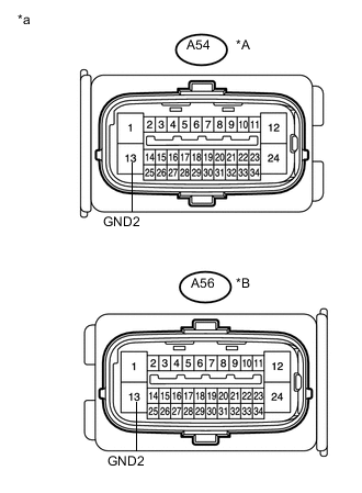
Text in Illustration *A except LHD with CVT *B for LHD with CVT *a Front view of wire harness connector
(to Brake actuator assembly (Skid control ECU))
Disconnect the A54 or A56 brake actuator assembly (skid control ECU) connector.
-
Measure the resistance according to the value(s) in the table below.
Standard Resistance except LHD with CVT Tester Connection Condition Specified Condition A54-13 (GND2) - Body ground Always Below 1 Ω for LHD with CVT Tester Connection Condition Specified Condition A56-13 (GND2) - Body ground Always Below 1 Ω -
Reconnect the A54 or A56 brake actuator assembly (skid control ECU) connector.
A 
REPAIR OR REPLACE HARNESS OR CONNECTOR
B
REPLACE BRAKE ACTUATOR ASSEMBLY (SKID CONTROL ECU) Click here
C
REPLACE BRAKE ACTUATOR ASSEMBLY (SKID CONTROL ECU) Click here
-