ANTI-LOCK BRAKE SYSTEM, Diagnostic DTC:C1428
| DTC Code | DTC Name |
|---|---|
| C1428 | Motor Circuit Malfunction |
DESCRIPTION
| DTC NO. | DTC Detection Condition | Trouble Area |
|---|---|---|
| C1428 | With the ABS motor relay OFF and the ABS motor fail safe relay ON, an open in the motor circuit continues for 2 seconds or more. | Brake actuator assembly (Skid control ECU) |
WIRING DIAGRAM
Refer to DTCs C1427 Click here.
CAUTION / NOTICE / HINT
Note
-
When replacing the brake actuator assembly (skid control ECU) or deceleration sensor, be sure to perform deceleration sensor 0 point calibration and CVT oil pressure calibration after performing AT/CVT learned values initialization.
for K310 Click here
for K411 Click here
-
Inspect the fuses for circuits related to this system before performing the following inspection procedure.
-
Perform the test mode procedure after the initialization (perform the test mode start only after the brake actuator assembly (skid control ECU) is replaced).
Tech Tips
By performing the test mode start, the identification code of the brake actuator assembly (skid control ECU) is re-registered.
PROCEDURE
-
CHECK HARNESS AND CONNECTOR (GND2)
-
Turn the ignition switch off.
-
Make sure that there is no looseness at the locking part and the connecting part of the connectors.
-
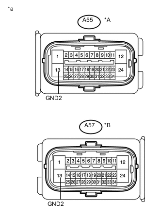
Text in Illustration *A except LHD with CVT *B for LHD with CVT *a Front view of wire harness connector
(to Brake actuator assembly (Skid control ECU))
Disconnect the A55 or A57 brake actuator assembly (skid control ECU) connector.
-
Measure the resistance according to the value(s) in the table below.
Standard Resistance except LHD with CVT Tester Connection Condition Specified Condition A55-13 (GND2) - Body ground Always Below 1 Ω for LHD with CVT Tester Connection Condition Specified Condition A57-13 (GND2) - Body ground Always Below 1 Ω -
Reconnect the A55 or A57 brake actuator assembly (skid control ECU) connector.
Result Result Proceed to NG A OK (for LHD) B OK (for RHD) C
A 
REPAIR OR REPLACE HARNESS OR CONNECTOR
B
REPLACE BRAKE ACTUATOR ASSEMBLY (SKID CONTROL ECU) Click here
C
REPLACE BRAKE ACTUATOR ASSEMBLY (SKID CONTROL ECU) Click here
-