ANTI-LOCK BRAKE SYSTEM, Diagnostic DTC:C1468, C1469, C146A, C146B
| DTC Code | DTC Name |
|---|---|
| C1468 | SFR Solenoid Circuit |
| C1469 | SFL Solenoid Circuit |
| C146A | SRR Solenoid Circuit |
| C146B | SRL Solenoid Circuit |
DESCRIPTION
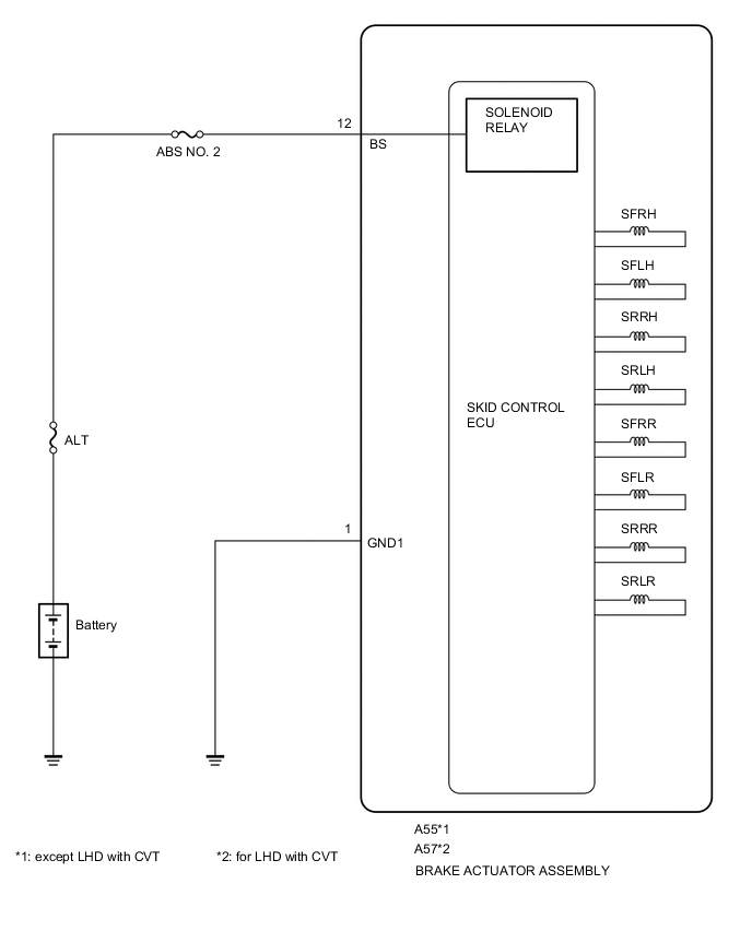
These solenoids turn on when signals are received from the brake actuator assembly (skid control ECU) and they control the pressure acting on the wheel cylinders to control the braking force.
| DTC NO. | DTC Detection Condition | Trouble Area |
|---|---|---|
| C1468 C1469 C146A C146B |
Open or short in the solenoid circuit continues for 0.05 seconds or more. |
|
WIRING DIAGRAM
CAUTION / NOTICE / HINT
Note
-
When replacing the brake actuator assembly (skid control ECU) or deceleration sensor, be sure to perform deceleration sensor 0 point calibration and CVT oil pressure calibration after performing AT/CVT learned values initialization.
for K310 Click here
for K411 Click here
-
Inspect the fuses for circuits related to this system before performing the following inspection procedure.
-
Perform the test mode procedure after the initialization (perform the test mode start only after the brake actuator assembly (skid control ECU) is replaced).
Tech Tips
By performing the test mode start, the identification code of the brake actuator assembly (skid control ECU) is re-registered.
PROCEDURE
-
RECONFIRM DTC
Tech Tips
This code is detected when a problem is identified in the brake actuator assembly.
The ABS motor relay is in the brake actuator assembly.
Therefore, ABS motor relay unit inspection cannot be performed. Be sure to check if the DTC is output before replacing the brake actuator assembly.
-
Turn the ignition switch off.
-
Clear the DTCs Click here.
-
Start the engine.
-
Drive the vehicle at a speed of 20 km/h (12 mph) or more for 30 seconds or more.
-
Check if the same DTC is recorded Click here.
Result Result Proceed to DTC (C1427) is not output A DTC (C1427) is output (for LHD) B DTC (C1427) is output (for RHD) C Tech Tips
-
If a speed signal of 6 km/h (4 mph) or more is input to the skid control ECU with the ignition switch ON and the stop light switch off, the ECU performs self diagnosis of the motor and solenoid circuits.
-
If the normal system code is output (no trouble codes are output), slightly jiggle the connectors, wire harness, and fuses of the brake actuator assembly. Make sure that no DTCs are output.
-
If any DTCs are output while jiggling a connector or wire harness of the brake actuator assembly (skid control ECU), inspect and repair the connector or wire harness.
-
The DTCs were probably output due to a bad connection of the connector terminal.
-
A 
CHECK FOR INTERMITTENT PROBLEMS (SYMPTOM SIMULATION) Click here
B
REPLACE BRAKE ACTUATOR ASSEMBLY (SKID CONTROL ECU) Click here
C
REPLACE BRAKE ACTUATOR ASSEMBLY (SKID CONTROL ECU) Click here
-