ANTI-LOCK BRAKE SYSTEM, Diagnostic DTC:C1243, C1245, C1279, C1418
| DTC Code | DTC Name |
|---|---|
| C1243 | Acceleration Sensor Stuck Malfunction |
| C1245 | Acceleration Sensor Output Malfunction |
| C1279 | Acceleration Sensor Output Voltage Malfunction (Test Mode DTC) |
| C1418 | Open or Short in Acceleration Sensor Circuit |
DESCRIPTION
| DTC No. | DTC Detection Condition | Trouble Area |
|---|---|---|
| C1243 | When vehicle speed decreases from 30 km/h (18 mph) to 0 km/h (0 mph), deceleration sensor signal does not change 16 times or more.. |
|
| C1245 | At vehicle speed of 30 km/h (18 mph) or more, difference between back and forth G value calculated using G sensor signals and back and forth G value calculated using vehicle speed, exceeds 0.35 G for 60 seconds or more. |
|
| C1418 | When any of following 1 through 3 detected:
|
|
| C1279 | Detected only during Test Mode. |
|
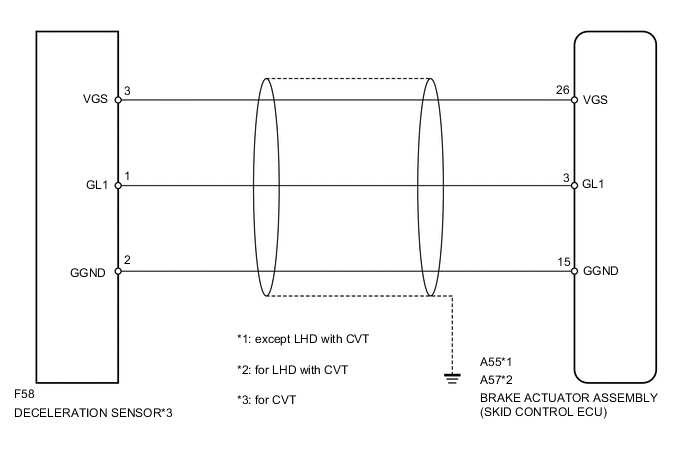
WIRING DIAGRAM
CAUTION / NOTICE / HINT
Note
-
When replacing the brake actuator assembly (skid control ECU) or deceleration sensor, be sure to perform deceleration sensor 0 point calibration and CVT oil pressure calibration after performing AT/CVT learned values initialization.
for K310 Click here
for K411 Click here
-
Perform the test mode procedure after the initialization (perform the test mode start only after the brake actuator assembly (skid control ECU) is replaced).
Tech Tips
By performing the test mode start, the identification code of the brake actuator assembly (skid control ECU) is re-registered.
PROCEDURE
-
READ VALUE USING INTELLIGENT TESTER (DECELERATION SENSOR)
-
Connect the intelligent tester to the DLC3.
-
Turn the ignition switch to ON.
-
Turn the intelligent tester on.
-
Enter the following menus: Chassis / ABS/VSC/TRC / Data List Click here.
-
According to the display on the tester, read the Data List.
ABS/VSC/TRC Tester Display Measurement Item / Range Normal Condition Diagnostic Note Deceleration sensor Deceleration sensor reading / Min.: -18.525 m/s2, Max.: 18.387 m/s2
- During deceleration/acceleration
Changes continuously
NG 
INSPECT DECELERATION SENSOR Click here
OK 
-
-
CHECK DTC
-
Clear the DTC Click here.
-
Turn the ignition switch to ON again and check if the same DTCs are recorded Click here.
Result Result Proceed to DTC not output A DTC output (for LHD) B DTC output (for RHD) C
A 
CHECK INTERMITTENT PROBLEMS Click here
B
REPLACE BRAKE ACTUATOR ASSEMBLY (SKID CONTROL ECU) Click here
C
REPLACE BRAKE ACTUATOR ASSEMBLY (SKID CONTROL ECU) Click here
-
-
INSPECT DECELERATION SENSOR
-
Remove the deceleration sensor Click here.
-
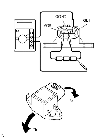
Text in Illustration *a Backward *b Forward Connect 3 dry cell batteries of 1.5 V in series.
-
Connect the VGS terminal to the batteries' positive (+) terminal and the GGND terminal to the batteries' negative (-) terminal.
-
Apply about 4.5 V between the VGS and GGND terminals.
Note
Do not apply voltage of 6 V or more to terminals VGS and GGND.
-
Check the output voltage of the GL1 terminal when the sensor is tilted forward and backward.
Standard Voltage: Tester Connection Sensor Condition Specified Condition 1 (GL1) - Batteries' negative (-) terminal Horizontal About 2.3 V 1 (GL1) - Batteries' negative (-) terminal Lean forward 0.4 to 2.3 V 1 (GL1) - Batteries' negative (-) terminal Lean backward 2.3 to 4.0 V Tech Tips
-
If the sensor is tilted too much it may show the wrong value.
-
If dropped, the sensor should be replaced with a new one.
-
Check and ensure the correct installation direction of the deceleration sensor.
-
NG
REPLACE DECELERATION SENSOR Click here
OK
-
-
CHECK HARNESS AND CONNECTOR (SKID CONTROL ECU-DECELERATION SENSOR)
-
Disconnect the A55 or A57 brake actuator assembly (skid control ECU) connector.
-
Disconnect the F58 deceleration sensor connector.
-
Measure the resistance according to the value(s) in the table below.
Standard Voltage (Check for Open) except LHD with CVT Tester Connection Condition Specified Condition A55- 26(VGS) - F58-3(VGS) Always Below 1 Ω A55-15 (GGND) - F58-2(GGND) Always Below 1 Ω A55-3 (GL1) - F58-1(GL1) Always Below 1 Ω for LHD with CVT Tester Connection Condition Specified Condition A57- 26(VGS) - F58-3(VGS) Always Below 1 Ω A57-15 (GGND) - F58-2(GGND) Always Below 1 Ω A57-3 (GL1) - F58-1(GL1) Always Below 1 Ω -
Measure the resistance according to the value(s) in the table below.
Standard Voltage (Check for Short) except LHD with CVT Tester Connection Condition Specified Condition A55- 26(VGS) - Body ground Always 10 kΩ or higher A55-15 (GGND) - Body ground Always 10 kΩ or higher A55-3 (GL1) - Body ground Always 10 kΩ or higher for LHD with CVT Tester Connection Condition Specified Condition A57- 26(VGS) - Body ground Always 10 kΩ or higher A57-15 (GGND) - Body ground Always 10 kΩ or higher A57-3 (GL1) - Body ground Always 10 kΩ or higher Result Result Proceed to NG A OK (for LHD) B OK (for RHD) C
A
REPAIR OR REPLACE HARNESS OR CONNECTOR
B
REPLACE BRAKE ACTUATOR ASSEMBLY (SKID CONTROL ECU) Click here
C
REPLACE BRAKE ACTUATOR ASSEMBLY (SKID CONTROL ECU) Click here
-