CONTINUOUSLY VARIABLE TRANSAXLE SYSTEM, Diagnostic DTC:P1585
| DTC Code | DTC Name |
|---|---|
| P1585 | Acceleration Sensor Circuit |
DESCRIPTION
The ECM determines the vehicle inclination based on a signal from the deceleration sensor or air bag sensor assembly (yaw rate sensor) to perform neutral control. If a malfunction is determined in the deceleration sensor or air bag sensor assembly (yaw rate sensor) based on a malfunction signal from the brake actuator assembly, the ECM cancels neutral control as a fail-safe function.
Tech Tips
-
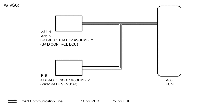
The signal of the airbag sensor assembly (yaw rate sensor) is sent to the brake actuator assembly via the CAN communication system.
-
If CAN communication DTCs are output, perform troubleshooting for those DTCs first.
| DTC No. | DTC Detection Condition
|
Trouble Area |
|---|---|---|
| P1585 |
|
|
|
||
|
||
|
||
|
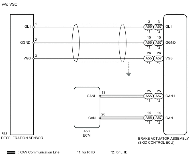
WIRING DIAGRAM
PROCEDURE
-
CHECK DTC OUTPUT (CAN COMMUNICATION SYSTEM)
-
Check for DTCs of the CAN communication system Click here.
Result Result Proceed to DTCs are not output A DTCs are output B
B 
GO TO CAN COMMUNICATION SYSTEM Click here
A 
-
-
READ VALUE USING INTELLIGENT TESTER (G SENSOR)
-
Connect the intelligent tester to the DLC3.
-
Turn the ignition switch to ON.
-
Turn the tester on.
-
Enter the following menus: Powertrain / Engine and ECT / Data List.
-
In accordance with the display on the tester, read the Data List.
Tester Display Measurement Item/Range Normal Condition Diagnostic Note G sensor Converted output voltage of deceleration sensor/
min.: 0 V
max.: 5 V
Displays converted voltage of deceleration sensor
-
Vehicle on level ground: 2.31 to 2.69 V
-
Decelerating: 0.5 to (2.5) V
-
Accelerating: (2.5) to 4.5 V
-
Open in deceleration sensor circuit: 4.5 V
-
Short in deceleration sensor circuit: 0.5 V or less
- Result Result Proceed to Data display is not within Normal Condition range (w/o VSC) A Data display is within Normal Condition range (w/o VSC) B Data display is not within Normal Condition range (w/ VSC) C Data display is within Normal Condition range (w/ VSC) D -
B 
CHECK DTC OUTPUT Click here
C
REPLACE AIR BAG SENSOR ASSEMBLY (YAW RATE SENSOR) Click here
D
REPLACE BRAKE ACTUATOR ASSEMBLY (SKID CONTROL ECU) Click here
A
-
-
CHECK HARNESS AND CONNECTOR (SKID CONTROL ECU - DECELERATION SENSOR)
-
Disconnect the A55 (for RHD) or A57 (for LHD) skid control ECU connector.
-
Disconnect the F58 deceleration sensor connector.
-
Measure the resistance according to the value(s) in the table below.
Standard Resistance (Check for Open) (for RHD) Tester Connection Condition Specified Condition A55-4 (GL1) - F58-1 (GL1) Always Below 1 Ω A55-7 (GGND) - F58-2 (GGND) Always Below 1 Ω A55-28 (VGS) - F58-3 (VGS) Always Below 1 Ω Standard Resistance (Check for Open) (for LHD) Tester Connection Condition Specified Condition A57-4 (GL1) - F58-1 (GL1) Always Below 1 Ω A57-7 (GGND) - F58-2 (GGND) Always Below 1 Ω A57-28 (VGS) - F58-3 (VGS) Always Below 1 Ω Standard Resistance (Check for Short) (for RHD) Tester Connection Condition Specified Condition A55-4 (GL1) - Body ground Always 10 kΩ or higher A55-7 (GGND) - Body ground Always 10 kΩ or higher A55-28 (VGS) - Body ground Always 10 kΩ or higher Standard Resistance (Check for Short) (for LHD) Tester Connection Condition Specified Condition A57-4 (GL1) - Body ground Always 10 kΩ or higher A57-7 (GGND) - Body ground Always 10 kΩ or higher A57-28 (VGS) - Body ground Always 10 kΩ or higher
NG
REPAIR OR REPLACE HARNESS OR CONNECTOR
OK
-
-
INSPECT DECELERATION SENSOR
-
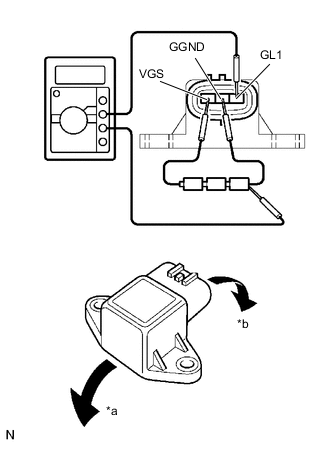
Text in Illustration *a Forward *b Backward Remove the deceleration sensor.
-
Connect 3 dry cell batteries of 1.5 V in series.
-
Connect the VGS terminal to the batteries' positive (+) terminal and the GGND terminal to the batteries' negative (-) terminal.
-
Apply about 4.5 V between the VGS and GGND terminals.
Note
Do not apply voltage of 6 V or more to terminals VGS and GGND.
-
Check the output voltage of the GL1 terminal when the sensor is tilted forward and backward.
Standard Voltage Tester Connection Sensor Condition Specified Condition 1 (GL1) - Batteries' negative (-) terminal Horizontal About 2.5 V Lean forward 0.5 to 2.5 V Lean backward 2.5 to 4.5 V Tech Tips
-
If the sensor is tilted too much it may show the wrong value.
-
If dropped, the sensor should be replaced with a new one.
-
Check and ensure the correct installation direction of the deceleration sensor.
-
NG
REPLACE DECELERATION SENSOR Click here
OK
-
-
CHECK DTC OUTPUT
-
Clear the DTCs Click here.
-
Perform a road test where the vehicle is driven at 30 km/ h (18 mph) or more, the brakes are applied at least 16 times and the vehicle is finally stopped.
-
Connect the intelligent tester to the DLC3.
-
Turn the ignition switch to ON.
-
Turn the tester on.
-
Enter the following menus: Powertrain / Engine and ECT / DTC / Current or Pending.
-
Read the DTCs using the tester.
Result Result Proceed to P1585 is output A P1585 is not output B Tech Tips
If any other codes besides DTC P1585 are output, perform troubleshooting for those DTCs first.
A
REPLACE BRAKE ACTUATOR ASSEMBLY (SKID CONTROL ECU) Click here
B
CHECK FOR INTERMITTENT PROBLEMS (SYMPTOM SIMULATION) Click here
-
-
REPLACE DECELERATION SENSOR
-
Replace the deceleration sensor Click here.
NEXT
-
-
PERFORM INITIALIZATION
Note
-
Performing reset memory will clear the learned values of both the yaw rate sensor (deceleration sensor 0 point calibration) and CVT oil pressure (CVT oil pressure calibration). Make sure to perform reset memory, yaw rate sensor 0 point calibration and CVT oil pressure calibration when replacing any of the parts shown in the following table:
Replaced Part
-
Continuously variable transaxle assembly
-
ECM
-
Skid control computer (w/o VSC)
-
Oil pressure sensor
-
Deceleration sensor (w/o VSC)
-
Airbag sensor assembly (Yaw rate sensor) (w/ VSC)
-
-
After performing reset memory, always perform yaw rate sensor (deceleration sensor 0 point) calibration first, and then CVT oil pressure calibration.
-
Always perform 0 point calibration with the vehicle on level ground.
-
Do not shake or vibrate the vehicle during 0 point calibration.
-
Using the intelligent tester, perform reset memory, deceleration sensor 0 point calibration and CVT oil pressure calibration Click here.
-
Check that no DTC is stored.
NEXT
END
-
-
REPLACE AIR BAG SENSOR ASSEMBLY (YAW RATE SENSOR)
Replace the air bag sensor assembly (yaw rate sensor) Click here.
NEXT
-
PERFORM INITIALIZATION
Note
-
Performing reset memory will clear the learned values of both the yaw rate sensor (deceleration sensor 0 point calibration) and CVT oil pressure (CVT oil pressure calibration). Make sure to perform reset memory, yaw rate sensor 0 point calibration and CVT oil pressure calibration when replacing any of the parts shown in the following table:
Replaced Part
-
Continuously variable transaxle assembly
-
ECM
-
Skid control computer (w/o VSC)
-
Oil pressure sensor
-
Deceleration sensor (w/o VSC)
-
Airbag sensor assembly (Yaw rate sensor) (w/ VSC)
-
-
After performing reset memory, always perform yaw rate sensor (deceleration sensor 0 point) calibration first, and then CVT oil pressure calibration.
-
Always perform 0 point calibration with the vehicle on level ground.
-
Do not shake or vibrate the vehicle during 0 point calibration.
-
Using the intelligent tester, perform reset memory, deceleration sensor 0 point calibration and CVT oil pressure calibration Click here.
-
Check that no DTC is stored.
NEXT
END
-