STOP AND START SYSTEM, Diagnostic DTC:P1538
| DTC Code | DTC Name |
|---|---|
| P1538 | Circuit Malfunction between AT Oil Pump and Stop and Start ECU |
DESCRIPTION
When the engine automatically stops, the mechanical oil pump of the continuously variable transaxle assembly also stops.
For a smooth start of the vehicle, during the period between the engine automatic stop and vehicle restart, the oil pressure in the continuously variable transaxle assembly is maintained by operating the oil with pump motor assembly.
The engine stop and start ECU supplies power to the oil pump with motor assembly (oil pump motor) with a command signal from the OPO terminal, activating the oil pump assembly (oil pump motor) with a command signal from the OPM1 terminal.
Oil pump speed signal from the oil pump with motor assembly (oil pump motor) is sent to the engine stop and start ECU via the NOPM signal line.
| DTC No. | DTC Detection Condition | Trouble Area |
|---|---|---|
| P1538 | The following condition continues for 2 seconds or more (1 trip detection logic):
|
|
| The following condition continues for 1 second or more (2 trip detection logic):
|
|
*: Since each information can be confirmed by freeze frame data, record the freeze frame data before deleting the diagnosis code.
Tech Tips
DTCs for the Stop and Start system are not cleared even if the malfunction has been repaired. After repairing the malfunction, be sure to clear the DTCs Click here.
-
After troubleshooting, perform the following steps to recheck for DTCs.
Tech Tips
-
If the battery terminal has been disconnected, the stop and start will be prohibited. In this case, drive the vehicle for 15 to 40 minutes to permit the stop and start operation.
-
Allow the engine to idle for 3 minutes after the engine warms up and check that the engine speed is within 50 rpm of the target idle speed.
-
Connect the GTS to the DLC3.
-
Clear the DTCs Click here.
-
Start the engine and warm it up.
-
Drive the vehicle at 7 km/h (4.3 mph) or more.
CAUTION:
When performing the confirmation driving pattern, obey all speed limits and traffic laws.
-
Stop the vehicle, allow the engine to stop due to stop and start system control (with the shift lever in D).
-
Release the brake pedal to allow the engine to restart (with the shift lever in D).
Tech Tips
If the engine cranks slowly when the engine is restarted, it can be determined that battery voltage is low.
-
Check that no DTCs are output Click here.
-
-
Check if the Stop and Start system operates normally.
Tech Tips
If the battery terminal has been disconnected, the stop and start will be prohibited. In this case, drive the vehicle for 15 to 40 minutes to permit the stop and start operation.
-
Warm up the engine.
-
Turn the air conditioning system off.
-
Drive the vehicle at 7 km/h (4.3 mph) or more.
CAUTION:
When performing the confirmation driving pattern, obey all speed limits and traffic laws.
-
Stop the vehicle, allow the engine to stop due to stop and start system control (with the shift lever in D).
-
Release the brake pedal to allow the engine to restart (with the shift lever in D).
-
WIRING DIAGRAM
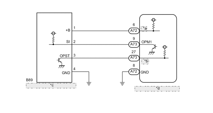
| *a | OPO |
| *b | NOPM |
| *c | Oil Pump with Motor Assembly |
| *d | Engine Stop and Start ECU |
CAUTION / NOTICE / HINT
Note
-
If the engine stop and start ECU is being replaced, register the previously recorded number of starter operations into the new engine stop and start ECU Click here.
-
After the engine stop and start ECU is replaced or after an air conditioner kit is installed, clear the A/C information stored in the engine stop and start ECU Click here.
-
After the engine stop and start ECU or airbag sensor assembly (yaw rate sensor) is replaced, initialize and calibrate 0 point of deceleration sensor Click here.
-
When the CVT fluid has been drained, or when removing or installing the oil pump with motor assembly (oil pump motor), bleed the air from the oil pump with motor assembly (oil pump motor) Click here.
Tech Tips
Using the GTS, read the freeze frame data before troubleshooting. System condition information is recorded as freeze frame data the moment a DTC is stored. This information can be useful when troubleshooting.
PROCEDURE
-
READ FREEZE FRAME DATA
-
Connect the GTS to the DLC3.
-
Turn the ignition switch to ON.
-
Turn the GTS on.
-
Using the GTS confirm the vehicle conditions recorded in the freeze frame data which were present when the DTC was stored Click here.
Result Freeze Frame Data Item Proceed to Status of O/P Signal 1 A Status of O/P Signal 2 B
B 
PERFORM ACTIVE TEST USING GTS (Activate the AT Oil Pump (Lo)) Click here
A 
-
-
CHECK HARNESS AND CONNECTOR (ENGINE STOP AND START ECU - OIL PUMP WITH MOTOR ASSEMBLY)
-
Disconnect the A72 and A73 engine stop and start ECU connector.
-
Disconnect the B89 oil pump with motor assembly connector.
-
Measure the resistance according to the value(s) in the table below.
Standard Resistance Tester Connection Condition Specified Condition A73-27 (NOPM) - B89-3 (OPST) Always Below 1 Ω A73-27 (NOPM) or B89-3 (OPST) - Body ground Always 10 kΩ or higher A72-6 (OPO) or B89-1 (+B) - Body ground Always 10 kΩ or higher
NG 
REPAIR OR REPLACE HARNESS OR CONNECTOR
OK
-
-
INSPECT ENGINE STOP AND START ECU
-
Disconnect the B89 oil pump with motor assembly connector.
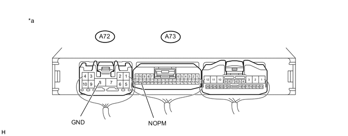
Text in Illustration *a Component with harness connected
(Engine stop and start ECU)
- - -
Turn the ignition switch to ON.
-
Measure the voltage according to the value(s) in the table below.
Standard Voltage Tester Connection Condition Specified Condition A73-27 (NOPM) - A72-8 (GND) Ignition switch ON 10 to 14 V
OK
REPLACE OIL PUMP WITH MOTOR ASSEMBLY
NG
REPLACE ENGINE STOP AND START ECU Click here
-
-
PERFORM ACTIVE TEST USING GTS (Activate the AT Oil Pump (Lo))
Note
Be sure to perform Active Test after the engine is warmed up, since the oil pump motor cannot operate normally when the CVT fluid temperature is low.
-
Connect the GTS to the DLC3.
-
Turn the ignition switch to ON.
-
Turn the GTS on.
-
Enter the following menus: Powertrain / Stop and Start / Active Test / AT Oil Pump (Lo).
-
During engine stop, turn the ignition switch to ON, and perform Active Test to confirm an operating sound and vibration from the oil pump with motor assembly.
Result AT Oil Pump (Lo) Operating sound and vibration ON Heard and felt OFF Unheard and unfelt
NG
CHECK HARNESS AND CONNECTOR (ENGINE STOP AND START ECU - OIL PUMP WITH MOTOR ASSEMBLY) Click here
OK
-
-
INSPECT ENGINE STOP AND START ECU
-
Connect an oscilloscope to the NOPM and GND terminals of the engine stop and start ECU connector.
Text in Illustration *a Component with harness connected
(Engine stop and start ECU)
- - -
Connect the GTS to the DLC3.
-
Turn the ignition switch to ON.
-
Turn the GTS on.
-
Enter the following menus: Powertrain / Stop and Start / Active Test / AT Oil Pump (Lo).
-
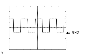
Check the NOPM waveform during the Active Test
Item Condition Tester connection NOPM - GND Tool setting 5 V/DIV, 5 ms/DIV Condition When performing the AT Oil Pump (Lo) of the Active Test OK A rectangular waveform similar to that shown in the illustration is output, and no noise is heard and no vibration is felt.
OK
REPLACE ENGINE STOP AND START ECU Click here
NG
-
-
INSPECT OIL PUMP WITH MOTOR ASSEMBLY
-
Disconnect the B89 oil pump with motor assembly connector.
-
Turn the ignition switch to ON.
-
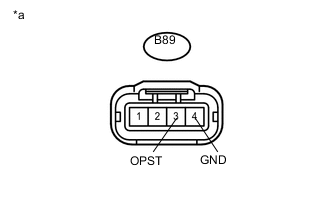
Text in Illustration *a Front view of wire harness connector
(to Oil Pump with Motor Assembly)
Measure the voltage according to the value(s) in the table below.
Standard Voltage Item Condition Condition B89-3 (OPST) - B89-4 (GND) IG ON 10 to 14 V
OK
REPLACE OIL PUMP WITH MOTOR ASSEMBLY
NG
-
-
CHECK HARNESS AND CONNECTOR (ENGINE STOP AND START ECU - OIL PUMP WITH MOTOR ASSEMBLY)
-
Disconnect the A73 engine stop and start ECU connector.
-
Disconnect the B89 oil pump with motor assembly connector.
-
Measure the resistance according to the value(s) in the table below.
Standard Resistance Tester Connection Condition Specified Condition A73-27 (NOPM) - B89-3 (OPST) Always Below 1 Ω A73-27 (NOPM) or B89-3 (OPST) - Body ground Always 10 kΩ or higher
OK
REPLACE ENGINE STOP AND START ECU Click here
NG
REPAIR OR REPLACE HARNESS OR CONNECTOR
-
-
CHECK HARNESS AND CONNECTOR (ENGINE STOP AND START ECU - OIL PUMP WITH MOTOR ASSEMBLY)
-
Disconnect the A72 engine stop and start ECU connector.
-
Disconnect the B89 oil pump with motor assembly connector.
-
Measure the resistance according to the value(s) in the table below.
Standard Resistance Tester Connection Condition Specified Condition A72-6 (OPO) - B89-1 (+B) Always Below 1 Ω A72-6 (OPO) or B89-1 (+B) - Body ground Always 10 kΩ or higher
NG
REPAIR OR REPLACE HARNESS OR CONNECTOR
OK
-
-
CHECK HARNESS AND CONNECTOR (ENGINE STOP AND START ECU - OIL PUMP WITH MOTOR ASSEMBLY)
-
Disconnect the B89 oil pump with motor assembly connector.
-
Measure the resistance according to the value(s) in the table below.
Standard Resistance Tester Connection Condition Specified Condition B89-4 (GND) - Body ground Always Below 1 Ω
NG
REPAIR OR REPLACE HARNESS OR CONNECTOR
OK
-
-
INSPECT ENGINE STOP AND START ECU
-
Disconnect the B89 oil pump with motor assembly connector.
Text in Illustration *a Component with harness connected
(Engine stop and start ECU)
- - -
Connect the GTS to the DLC3.
-
Turn the ignition switch to ON.
-
Turn the GTS on.
-
Enter the following menus: Powertrain / Stop and Start / Active Test / AT Oil Pump (Lo).
-
Measure the voltage according to the value(s) in the table below.
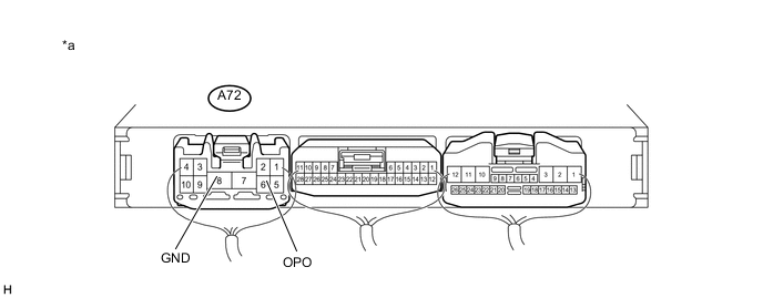
Standard Voltage Tester Connection Condition Specified Condition A72-6 (OPO) - A72-8 (GND) When performing the AT Oil Pump (Lo) of the Active Test 10 to 14 V
NG
REPLACE ENGINE STOP AND START ECU Click here
OK
-
-
CHECK HARNESS AND CONNECTOR (ENGINE STOP AND START ECU - OIL PUMP WITH MOTOR ASSEMBLY)
-
Disconnect the A73 engine stop and start ECU connector.
-
Disconnect the B89 oil pump with motor assembly connector.
-
Measure the resistance according to the value(s) in the table below.
Standard Resistance Tester Connection Condition Specified Condition A73-9 (OPM1) - B89-2 (SI) Always Below 1 Ω A73-9 (OPM1) or B89-2 (SI) or Body ground Always 10 kΩ or higher
NG
REPAIR OR REPLACE HARNESS OR CONNECTOR
OK
-
-
INSPECT OIL PUMP WITH MOTOR ASSEMBLY
-
Connect an oscilloscope to the OPM1 and GND terminals of the engine stop and start ECU connector.
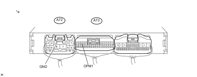
Text in Illustration *a Component with harness connected
(Engine stop and start ECU)
- - -
Connect the GTS to the DLC3.
-
Turn the ignition switch to ON.
-
Turn the GTS on.
-
Enter the following menus: Powertrain / Stop and Start / Active Test / AT Oil Pump (Lo).
-
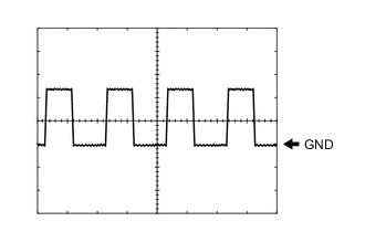
Check the OPM1 waveform during the Active Test
Item Condition Tester connection OPM1 - GND Tool setting 5 V/DIV, 5 ms/DIV Condition When performing the AT Oil Pump (Lo) of the Active Test OK A rectangular waveform similar to that shown in the illustration is output, and no noise is heard and no vibration is felt.
OK
REPLACE ENGINE STOP AND START ECU Click here
NG
REPLACE OIL PUMP WITH MOTOR ASSEMBLY
-