STOP AND START SYSTEM, Diagnostic DTC:P1539
| DTC Code | DTC Name |
|---|---|
| P1539 | AT Oil Pump |
DESCRIPTION
Refer to DTC P1539 Click here
| DTC No. | DTC Detection Condition | Trouble Area |
|---|---|---|
| P1539 | The following condition continues for 2 seconds or more (2 trip detection logic):
|
|
| The following condition continues for 2 seconds or more (2 trip detection logic):
|
|
*: Since each information can be confirmed by freeze frame data, record the freeze frame data before deleting the diagnosis code.
-
After troubleshooting, perform the following steps to recheck for DTCs.
Tech Tips
-
If the battery terminal has been disconnected, the stop and start will be prohibited. In this case, drive the vehicle for 15 to 40 minutes to permit the stop and start operation.
-
Allow the engine to idle for 3 minutes after the engine warms up and check that the engine speed is within 50 rpm of the target idle speed.
-
Connect the GTS to the DLC3.
-
Clear the DTCs Click here.
-
Start the engine and warm it up.
-
Drive the vehicle at 7 km/h (4.3 mph) or more.
CAUTION:
When performing the confirmation driving pattern, obey all speed limits and traffic laws.
-
Stop the vehicle, allow the engine to stop due to stop and start system control (with the shift lever in D).
-
Release the brake pedal to allow the engine to restart (with the shift lever in D).
Tech Tips
If the engine cranks slowly when the engine is restarted, it can be determined that battery voltage is low.
-
Check that no DTCs are output Click here.
-
-
Check if the Stop and Start system operates normally.
Tech Tips
If the battery terminal has been disconnected, the stop and start will be prohibited. In this case, drive the vehicle for 15 to 40 minutes to permit the stop and start operation.
-
Warm up the engine.
-
Turn the air conditioning system off.
-
Drive the vehicle at 7 km/h (4.3 mph) or more.
CAUTION:
When performing the confirmation driving pattern, obey all speed limits and traffic laws.
-
Stop the vehicle, allow the engine to stop due to stop and start system control (with the shift lever in D).
-
Release the brake pedal to allow the engine to restart (with the shift lever in D).
-
WIRING DIAGRAM
Refer to DTC P1538 Click here.
CAUTION / NOTICE / HINT
Note
-
If the engine stop and start ECU is being replaced, register the previously recorded number of starter operations into the new engine stop and start ECU Click here.
-
After the engine stop and start ECU is replaced or after an air conditioner kit is installed, clear the A/C information stored in the engine stop and start ECU Click here.
-
When the engine stop and start ECU or components of the VSC system are replaced, initialization/obtainment of 0 point learning information is performed for the engine stop and start ECU Click here.
-
When the CVT fluid has been drained, or when removing or installing the oil pump with motor assembly (oil pump motor), bleed the air from the oil pump with motor assembly (oil pump motor) Click here.
Tech Tips
-
Using the GTS, read the freeze frame data before troubleshooting. System condition information is recorded as freeze frame data the moment a DTC is stored. This information can be useful when troubleshooting.
-
When P1538 and P1539 are simultaneously output, check P1538 first Click here.
PROCEDURE
-
CONFIRM DTC OUTPUT
-
Connect the GTS to the DLC3.
-
Turn the ignition switch to ON.
-
Turn the GTS on.
-
Check for DTCs and read the freeze frame data.
Result Result Proceed to Only DTC P1539 is output A DTC P1538 and P1539 are output B
B 
GO TO DTC CHART (P1538)
A 
-
-
PERFORM ACTIVE TEST USING GTS (Activate the AT Oil Pump (Lo))
-
Drive the vehicle to warm up the engine and CVT.
-
Connect the GTS to the DLC3.
-
Turn the ignition switch to ON.
-
Turn the GTS on.
-
Enter the following menus: Powertrain / Stop and Start / Active Test / AT Oil Pump (Lo).
-
Connect an oscilloscope to the NOPM and GND terminals of the engine stop and start ECU connector.
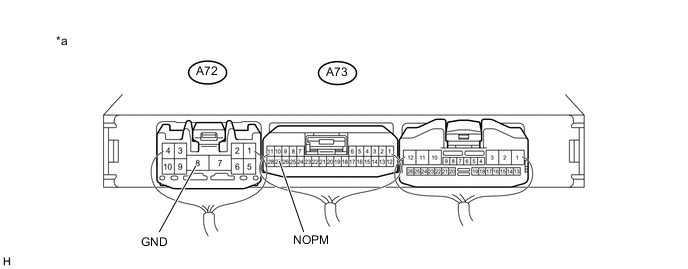
Text in Illustration *a Component with harness connected
(Engine stop and start ECU)
- - -
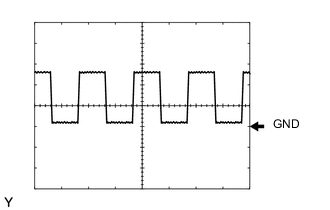
Check the NOPM waveform during the Active Test
Item Condition Tester connection NOPM - GND Tool setting 5 V/DIV, 5 ms/DIV Condition When performing the AT Oil Pump (Lo) of the Active Test Result Freeze Frame Data Item Proceed to 17 to 200 Hz
( Normal waveform)
A Other than 17 to 200 Hz
(abnormal waveform)
B Noise in a normal waveform C
B
REPLACE OIL PUMP WITH MOTOR ASSEMBLY
C
REPAIR OR REPLACE HARNESS OR CONNECTOR
A
-
-
CLEAR DTC
Note
Before deleting the diagnosis code, be sure to store the freeze frame data.
-
Clear the DTC Click here.
NEXT
-
-
CONFIRM DTC OUTPUT
-
Drive the vehicle with a stop-and-go city drive pattern for more than 15 minutes.
-
Connect the GTS to the DLC3.
-
Turn the ignition switch to ON.
-
Turn the GTS on.
-
Check for DTCs and read the freeze frame data.
Result Result Proceed to DTC P1539 is output A DTC is not output B Tech Tips
When the diagnosis code is not displayed, there is a possibility that the oil pump motor cannot run because of a blockage in the hydraulic circuit temporarily.
B
END
A
-
-
READ VALUE USING GTS (A/T OIL PRESSURE (CVT OIL PRESSURE))
-
Connect the GTS to the DLC3.
-
Turn the ignition switch to ON.
-
Turn the GTS on.
-
Enter the following menus: Powertrain / Engine and ECT / Data List.
-
In accordance with the display on the GTS, read the Data List.
Result Result Proceed to Data display is within Normal Condition range A Data display is not within Normal Condition range B
A
REPLACE ENGINE STOP AND START ECU Click here
B
REPLACE OIL PUMP WITH MOTOR ASSEMBLY
-