STOP AND START SYSTEM, Diagnostic DTC:P1603
| DTC Code | DTC Name |
|---|---|
| P1603 | Engine Stall History |
DESCRIPTION
If the engine stalls or engine start fails while the stop and start control is operating, DTC P1603 is stored. Using the GTS, the freeze frame data recorded the moment the DTC is stored can be read. Serviceability has been enhanced by enabling the cause of an engine stall or engine start failure which occurred while the stop and start control was operating to be checked using the freeze frame data.
| DTC No. | DTC Detection Condition | Trouble Area |
|---|---|---|
| P1603 | The following conditions continue for 0.5 seconds or more (1 trip detection logic):
|
|
CAUTION / NOTICE / HINT
Note
-
Before replacing the engine stop and start ECU, read the number of starter operations and write it into a new engine stop and start ECU Click here.
-
After replacing the starter assembly, perform initialization of the number of starter operations stored in the engine stop and start ECU Click here.
-
After replacing the engine stop and start ECU or air conditioning amplifier assembly, reset and perform learning of the air conditioning information in the engine stop and start ECU Click here.
-
After replacing the engine stop and start ECU or airbag sensor assembly, perform deceleration sensor zero point clear and calibration Click here.
-
Inspect the fuses for circuits related to this system before performing the following inspection procedure.
Tech Tips
-
If other DTCs are output, perform troubleshooting for this DTC first.
-
Unlike other DTCs that are stored due to a malfunction in parts, circuits or systems, DTC P1603 allows determination of a malfunctioning part according to problem symptoms and the freeze frame data related to a problem recognized by the customer. As this DTC may be stored due to an operation by the customer, it is not necessary to service the vehicle unless the customer recognized a problem. Clear DTCs and return the vehicle to the customer.
-
Using the GTS, read the freeze frame data before troubleshooting. System condition information is recorded as freeze frame data the moment a DTC is stored. This information can be useful when troubleshooting.
-
Causes of engine stall or engine start failure while the engine is stopped by stop and start control:
-
If engine hood is opened while the engine is stopped by stop and start control, the engine will stall.
The number of engine stalls due to the engine hood being opened while the engine is stopped by stop and start control is stored in the engine stall history.
-
If a collision detection signal is received from the airbag sensor assembly while the engine is stopped by stop and start control, the engine will stall.
-
If a collision detection signal is received from the airbag sensor assembly while the engine is restarted by stop and start control, the engine will stall.
-
If low battery voltage is detected while the engine is stopped by stop and start control, the engine will stall.
-
If any problems that cause engine start failure and are not indicated by DTCs which occurred while the engine is stopped by stop and start control, the engine will not start.
PROCEDURE
-
CHECK DTC OUTPUT (SFI SYSTEM)
-
Connect the GTS to the DLC3.
-
Turn the ignition switch to ON.
-
Turn the GTS on.
-
Enter the following menus: Powertrain / Engine and ECT / Trouble Codes
-
Read the DTCs.
Result Result Proceed to SFI system DTCs are output A SFI system DTC P1604 is output and starter assembly operates B DTCs other than SFI system DTC P1604 are output C
B 
GO TO SFI SYSTEM Click here
C
GO TO DTC CHART Click here
A 
-
-
CHECK FREEZE FRAME DATA
Note
The freeze frame data is cleared when DTCs are cleared. Be sure to make a note of necessary data in advance.
Tech Tips
Using the time-series freeze frame data, confirm the freeze frame data recorded the moment the DTC was stored and after the DTC was stored. This information can be useful when troubleshooting.
-
According to the prompts on the GTS screen, read the time-series freeze frame data to confirm the vehicle conditions when an engine stall occurred while the stop and start control was operating.
-
Check the freeze frame data for engine stall history and engine start failure.
Result Tester Display Result Proceed to Engine Stall History during S&S (Hood Open) Yes A Engine Stall History during S&S (Collision or Battery Low) Yes B Engine Stall History during Engine Starting (Collision) Yes Engine Start Fail Yes C
B 
CHECK VEHICLE CONDITION (COLLISION HISTORY) Click here
C
CHECK HARNESS AND CONNECTOR (ENGINE STOP AND START ECU - ST/MGC, ST2 RELAY) Click here
A
-
-
READ VALUE USING GTS (HOOD COURTESY SWITCH)
Note
Before performing this step, check that the engine hood can be opened by pulling the hood lock control cable.
-
Connect the GTS to the DLC3.
-
Turn the ignition switch to ON.
-
Turn the GTS on.
-
Enter the following menus: Powertrain / Stop and Start / Data List / Hood Courtesy Switch.
-
Read the value displayed on the GTS when the engine hood is opened and closed.
OK Tester Display Condition Normal Condition Hood Courtesy Switch Engine hood is closed ON Engine hood is open OFF Result Result Proceed to NG A OK B
B
USE SIMULATION METHOD TO CHECK Click here
A
-
-
INSPECT HOOD LOCK ASSEMBLY (ENGINE HOOD COURTESY SWITCH)
-
Inspect the hood lock assembly (engine hood courtesy switch) Click here.
NG
REPLACE HOOD LOCK ASSEMBLY (ENGINE HOOD COURTESY SWITCH)
OK
-
-
CHECK HARNESS AND CONNECTOR (HOOD LOCK ASSEMBLY - BODY GROUND)
-
Disconnect the A32 engine hood courtesy switch connector.
-
Measure the resistance according to the value(s) in the table below.
Standard Resistance Tester Connection Condition Specified Condition A32-1 - Body ground Always Below 1 Ω
NG
REPAIR OR REPLACE HARNESS OR CONNECTOR
OK
-
-
CHECK HARNESS AND CONNECTOR (ENGINE STOP AND START ECU - HOOD LOCK ASSEMBLY)
-
Disconnect the A32 engine hood courtesy switch connector.
-
Disconnect the A73 engine stop and start ECU connector.
-
Measure the resistance according to the value(s) in the table below.
Standard Resistance Tester Connection Condition Specified Condition A73-7 (BNT1) - A32-2 Always Below 1 Ω A73-7 (BNT1) or A32-2 - Body ground Always 10 kΩ or higher
OK
REPLACE ENGINE STOP AND START ECU Click here
NG
REPAIR OR REPLACE HARNESS OR CONNECTOR
-
-
CHECK VEHICLE CONDITION (COLLISION HISTORY)
-
Check if the vehicle was in a collision when the engine stalled.
Result Result Proceed to Vehicle was not in collision when engine stalled (Freeze Frame Data "Engine Stall History during S&S (Collision or Battery Low)" Yes) A Vehicle was not in collision when engine stalled (Freeze Frame Data "Engine Stall History during Engine Starting (Collision)" Yes) B Vehicle was in collision when engine stalled C Tech Tips
When "Engine Stall History during S&S (Collision or Battery Low)" or "Engine Stall History during Engine Starting (Collision)" is stored:
This may have been stored because the vehicle was in a collision or a collision detection signal was input while the stop and start control was operating.
B
GO TO AIRBAG SYSTEM
C
END (ENGINE STALLED BECAUSE COLLISION DETECTION SIGNAL IS RECEIVED)
A
-
-
CHECK BATTERY VOLTAGE
-
Measure the voltage according to the value(s) in the table below.
Standard Voltage Tester Connection Condition Specified Condition Positive (+) battery terminal - Negative (-) battery terminal Ignition switch ON 11 to 14 V
NG
GO TO CHARGING SYSTEM
OK
-
-
CHECK HARNESS AND CONNECTOR (ENGINE STOP AND START ECU - BATTERY)
-
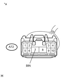
Text in Illustration *a Front view of wire harness connector
(to Engine Stop and Start ECU)
Disconnect the A72 engine stop and start ECU connector.
-
Measure the voltage according to the value(s) in the table below.
Standard Voltage Tester Connection Condition Specified Condition A72-7 (BIN) - Body ground Always 9.5 to 14 V
NG
REPAIR OR REPLACE HARNESS OR CONNECTOR
OK
-
-
CHECK HARNESS AND CONNECTOR (ENGINE STOP AND START ECU - BODY GROUND)
-
Disconnect the A72 engine stop and start ECU connector.
-
Measure the resistance according to the value(s) in the table below.
Standard Resistance Tester Connection Condition Specified Condition A72-8 (GND) - Body ground Always Below 1 Ω
NG
REPAIR OR REPLACE HARNESS OR CONNECTOR
OK
-
-
CHECK HARNESS AND CONNECTOR (NEGATIVE (-) BATTERY TERMINAL - BODY GROUND)
-
Disconnect the negative (-) battery terminal.
-
Measure the resistance according to the value(s) in the table below.
Standard Resistance Tester Connection Condition Specified Condition Negative (-) battery terminal - Body ground Always Below 1 Ω
OK
REPLACE ENGINE STOP AND START ECU Click here
NG
REPAIR OR REPLACE HARNESS OR CONNECTOR
-
-
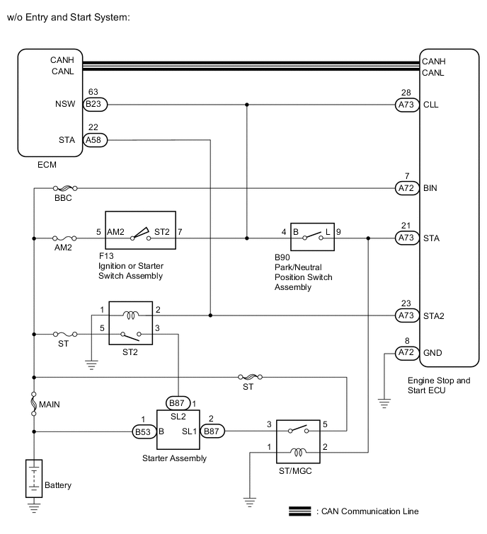
CHECK HARNESS AND CONNECTOR (ENGINE STOP AND START ECU - ST/MGC, ST2 RELAY)
-
Disconnect the A72 and A73 engine stop and start ECU connectors.
-
Disconnect the A58 ECM connector.
-
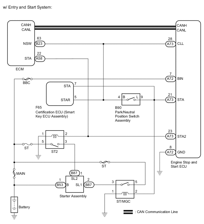
Disconnect the F65 certification ECU (smart key ECU assembly) connector (w/ Entry and Start System).
-
Disconnect the B90 park/neutral position switch connector.
-
Remove the ST/MGC relays from the No. 2 engine room relay block.
-
Remove the ST2 relays from the engine room relay block.
-
Remove the BBC fuse from the engine room relay block.
-
Measure the resistance according to the value(s) in the table below.
Standard Resistance Tester Connection Condition Specified Condition A73-21 (STA) - ST/MGC relay holder 2 Always Below 1 Ω A73-23 (STA2) - ST2 relay holder 2 Always Below 1 Ω A73-21 (STA) or ST/MGC relay holder 2 - Body ground Always 10 kΩ or higher A73-23 (STA2) or ST2 relay holder 2 - Body ground Always 10 kΩ or higher A72-7 (BIN) - A73-21 (STA) Always 10 kΩ or higher A72-7 (BIN) - A73-23 (STA2) Always 10 kΩ or higher
NG
REPAIR OR REPLACE HARNESS OR CONNECTOR
OK
-
-
CHECK HARNESS AND CONNECTOR (ST/MGC, ST2 RELAY - BODY GROUND)
-
Remove the ST/MGC relay from the No. 2 engine room relay block.
-
Remove the ST2 relay from the engine room relay block.
-
Measure the resistance according to the value(s) in the table below.
Standard Resistance Tester Connection Condition Specified Condition ST/MGC relay holder 1 - body ground Always Below 1 Ω ST2 relay holder 1 - body ground Always Below 1 Ω
NG
REPAIR OR REPLACE HARNESS OR CONNECTOR
OK
-
-
CHECK HARNESS AND CONNECTOR (ST/MGC, ST2 RELAY - BATTERY)
-
Remove the ST/MGC relay from the No. 2 engine room relay block.
-
Remove the ST2 relay from the engine room relay block.
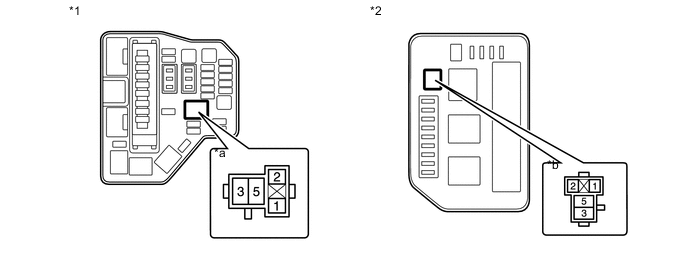
Text in Illustration *1 Engine Room Relay Block *2 No. 2 Engine Room Relay Block *a ST2 Relay Holder *b ST/MGC Relay Holder -
Measure the voltage according to the value(s) in the table below.
Standard Voltage Tester Connection Condition Specified Condition ST/MGC relay holder 5 - body ground Always 9.5 to 14 V ST2 relay holder 5 - body ground Always 9.5 to 14 V
NG
REPAIR OR REPLACE HARNESS OR CONNECTOR
OK
-
-
CHECK HARNESS AND CONNECTOR (STARTER ASSEMBLY - BATTERY)
-
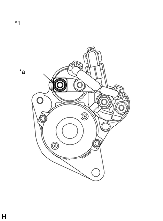
Text in Illustration *1 Starter Assembly *a B53 Measure the voltage according to the value(s) in the table below.
Standard Voltage Tester Connection Condition Specified Condition B53-1 - Body ground Always 9.5 to 14 V Note
Check in advance that the starter assembly connector B53 is not loose or disconnected.
NG
REPAIR OR REPLACE HARNESS OR CONNECTOR
OK
-
-
CHECK HARNESS AND CONNECTOR (STARTER ASSEMBLY - ST/MGC, ST2 RELAY)
-
Remove the ST/MGC relay from the No. 2 engine room relay block.
-
Remove the ST2 relay from the engine room relay block.
-
Disconnect the B87 starter assembly connector.
-
Measure the resistance according to the value(s) in the table below.
Standard Resistance Tester Connection Condition Specified Condition ST/MGC relay holder 3 - B87-2 Always Below 1 Ω ST2 relay holder 3 - B87-1 Always Below 1 Ω
NG
REPAIR OR REPLACE HARNESS OR CONNECTOR
OK
-
-
INSPECT ST/MGC RELAY
-
Inspect the ST/MGC relay Click here.
NG
REPLACE RELAY (ST/MGC RELAY)
OK
-
-
INSPECT ST2 RELAY
-
Inspect the ST2 relay Click here.
NG
REPLACE RELAY (ST2 RELAY)
OK
-
-
INSPECT STARTER ASSEMBLY
-
Inspect the starter assembly Click here.
OK
REPLACE ENGINE STOP AND START ECU Click here
NG
REPLACE STARTER ASSEMBLY Click here
-