STOP AND START SYSTEM, Diagnostic DTC:P161D
| DTC Code | DTC Name |
|---|---|
| P161D | Starter Delay Circuit |
DESCRIPTION
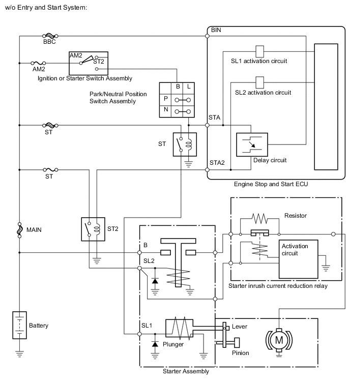
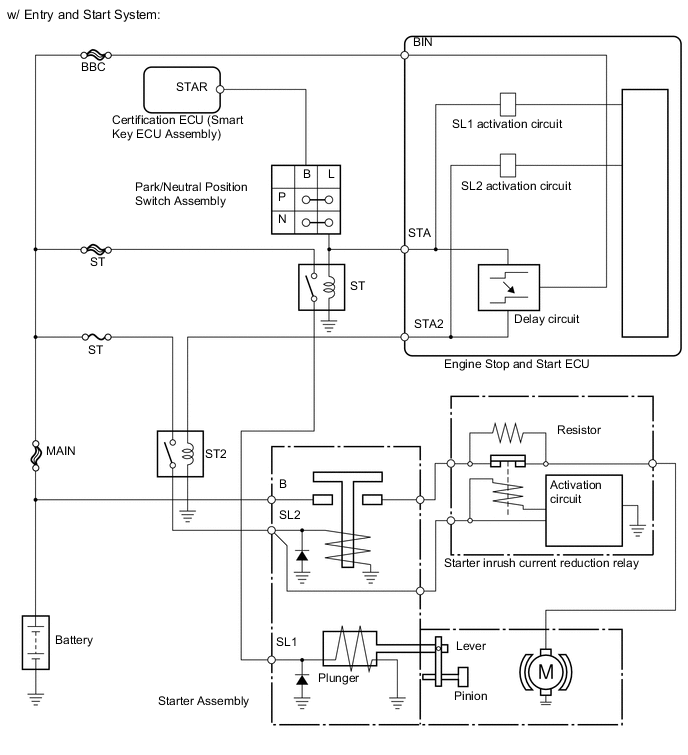
The engine stop and start ECU utilizes the starter delay circuit to activate the start pinion activation relay (ST relay), then the starter motor activation relay (ST/ST2 relay), and then operates the starter.
The engine stop and start ECU monitors the starter pinion activation relay (ST relay) and the starter motor activation relay (ST/ST2 relay) in order to check whether the internal transistor in the starter delay circuit is stuck ON. If the internal transistor in the starter delay circuit is stuck ON, DTC P161D is stored and the stop and start cancel indicator blinks. When the internal transistor in the starter delay circuit is stuck ON, the starter pinion activation relay (ST relay) and the starter motor activation relay (ST/ST2 relay) are turned on simultaneously.
| DTC No. | DTC Detection Condition | Trouble Area |
|---|---|---|
| P1610 |
|
Engine Stop and Start ECU |
-
After troubleshooting, perform the following steps to recheck for DTCs.
Tech Tips
-
If the battery terminal has been disconnected, the stop and start will be prohibited. In this case, drive the vehicle for 15 to 40 minutes to permit the stop and start operation.
-
Allow the engine to idle for 3 minutes after the engine warms up and check that the engine speed is within 50 rpm of the target idle speed.
-
Connect the GTS to the DLC3.
-
Clear the DTCs Click here.
-
Start the engine and warm it up.
-
Drive the vehicle at 7 km/h (4.3 mph) or more.
CAUTION:
When performing the confirmation driving pattern, obey all speed limits and traffic laws.
-
Stop the vehicle, allow the engine to stop due to stop and start system control (with the shift lever in D).
-
Release the brake pedal to allow the engine to restart (with the shift lever in D).
-
Check that no DTCs are output Click here.
-
-
Check if the Stop and Start system operates normally.
Tech Tips
If the battery terminal has been disconnected, the stop and start will be prohibited. In this case, drive the vehicle for 15 to 40 minutes to permit the stop and start operation.
-
Warm up the engine.
-
Turn the air conditioning system off.
-
Drive the vehicle at 7 km/h (4.3 mph) or more.
CAUTION:
When performing the confirmation driving pattern, obey all speed limits and traffic laws.
-
Stop the vehicle, allow the engine to stop due to stop and start system control (with the shift lever in D).
-
Release the brake pedal to allow the engine to restart (with the shift lever in D).
-
WIRING DIAGRAM
Refer to P1545 Click here.
CAUTION / NOTICE / HINT
Note
-
If the engine stop and start ECU is being replaced, register the previously recorded number of starter operations into the new engine stop and start ECU Click here.
-
After the engine stop and start ECU is replaced or after an air conditioner kit is installed, clear the A/C information stored in the engine stop and start ECU Click here.
-
After the engine stop and start ECU or airbag sensor assembly (yaw rate sensor) is replaced, initialize and calibrate 0 point of deceleration sensor Click here.
Tech Tips
Using the GTS, read the freeze frame data before troubleshooting. System condition information is recorded as freeze frame data the moment a DTC is stored. This information can be useful when troubleshooting.
PROCEDURE
-
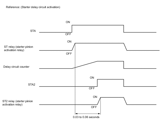
INSPECT ENGINE STOP AND START ECU
-
Connect an oscilloscope to the STA, STA2 and GND terminals of the engine stop and start ECU connector.
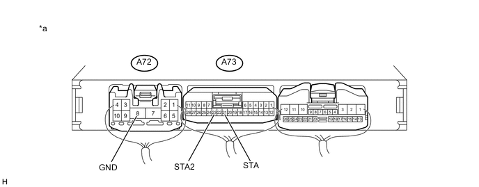
Text In Illustration *a Component with harness connected:
(Engine Stop and Start ECU)
- - -
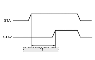
*1 0.016 seconds or more Check the waveform immediately after starting
Item Condition Tester connection STA - GND
STA2 - GND
Condition Engine starting by operating the ignition or starter switch assembly, or pushing the push start switch Result Tester Connection Condition Specified Condition Proceed to A73-21 (STA) - A72-8 (GND)
A73-23 (STA2) - A72-8 (GND)
Engine starting by operating the ignition or starter switch assembly, or pushing the push start switch Time from ST relay on to ST2 relay on is at least 0.016 seconds A Time from ST relay on to ST2 relay on is less than 0.016 seconds B
A 
USE SIMULATION METHOD TO CHECK Click here
B
REPLACE ENGINE STOP AND START ECU Click here
-