STOP AND START SYSTEM, Diagnostic DTC:P1644
| DTC Code | DTC Name |
|---|---|
| P1644 | ECU Internal Error |
DESCRIPTION
If a malfunction is detected in the starter circuit, the engine stop and start ECU stores DTC P1644 and illuminates the stop and start cancel indicator light.
| DTC No. | DTC Detection Condition | Trouble Area |
|---|---|---|
| P1644 | The following condition continues for 0.2 seconds or more (1 trip detection logic):
|
|
-
After troubleshooting, perform the following steps to recheck for DTCs.
Tech Tips
-
If the battery terminal has been disconnected, the stop and start will be prohibited. In this case, drive the vehicle for 15 to 40 minutes to permit the stop and start operation.
-
Allow the engine to idle for 3 minutes after the engine warms up and check that the engine speed is within 50 rpm of the target idle speed.
-
Connect the GTS to the DLC3.
-
Clear the DTCs Click here.
-
Start the engine and warm it up.
-
Drive the vehicle at 7 km/h (4.3 mph) or more.
CAUTION:
When performing the confirmation driving pattern, obey all speed limits and traffic laws.
-
Stop the vehicle, allow the engine to stop due to stop and start system control (with the shift lever in D).
-
Release the brake pedal to allow the engine to restart (with the shift lever in D).
Tech Tips
If the engine cranks slowly when the engine is restarted, it can be determined that battery voltage is low.
-
Check that no DTCs are output Click here.
-
-
Check if the Stop and Start system operates normally.
Tech Tips
If the battery terminal has been disconnected, the stop and start will be prohibited. In this case, drive the vehicle for 15 to 40 minutes to permit the stop and start operation.
-
Warm up the engine.
-
Turn the air conditioning system off.
-
Drive the vehicle at 7 km/h (4.3 mph) or more.
CAUTION:
When performing the confirmation driving pattern, obey all speed limits and traffic laws.
-
Stop the vehicle, allow the engine to stop due to stop and start system control (with the shift lever in D).
-
Release the brake pedal to allow the engine to restart (with the shift lever in D).
-
WIRING DIAGRAM
Refer to P1545 Click here.
CAUTION / NOTICE / HINT
Note
-
Before replacing the engine stop and start ECU, read the number of starter operations and write it into a new engine stop and start ECU Click here.
-
After replacing the engine stop and start ECU or air conditioning amplifier assembly, reset and perform learning of the air conditioning information in the engine stop and start ECU Click here.
-
After replacing the engine stop and start ECU or airbag sensor assembly, perform deceleration sensor zero point clear and calibration Click here.
-
Inspect the fuses for circuits related to this system before performing the following inspection procedure.
Tech Tips
-
Using the GTS, read the freeze frame data before troubleshooting. System condition information is recorded as freeze frame data the moment a DTC is stored. This information can be useful when troubleshooting.
-
If DTCs P060B and P1644 are output simultaneously, perform troubleshooting for DTC P060B (Analog to Digital Converter Malfunction) first as it may have caused DTC P1644 (ECU Internal Error) to be stored.
-
If DTCs P0617 and P1644 are output simultaneously, perform troubleshooting for DTC P0617 (Starter Relay Circuit High) first as it may have caused DTC P1644 (ECU Internal Error) to be stored.
-
If DTCs P0641 and P1644 are output simultaneously, perform troubleshooting for DTC P0641 (Sensor Reference Voltage "A" Circuit/Open) first as it may have caused DTC P1644 (ECU Internal Error) to be stored.
DTCs for the Stop and Start system are not cleared even if the malfunction has been repaired. After repairing the malfunction, be sure to clear the DTCs Click here.
PROCEDURE
-
CHECK ANY OTHER DTCS OUTPUT (IN ADDITION TO DTC P1644)
-
Connect the GTS to the DLC3.
-
Turn the ignition switch to ON.
-
Turn the GTS on.
-
Enter the following menus: Powertrain / Stop and Start / Trouble Codes.
-
Check for other DTCs.
Result Result Proceed to DTC P1644 is output A DTC P060B and DTC P1644 are output B DTC P0617 and DTC P1644 are output C DTC P0641 and DTC P1644 are output D
B 
GO TO DTC P060B CHART Click here
C
GO TO DTC P0617 CHART Click here
D
GO TO DTC P0641 CHART Click here
A 
-
-
CHECK HARNESS AND CONNECTOR (ENGINE STOP AND START ECU - ST/MGC RELAY)
-
Disconnect the F65 certification ECU (smart key ECU assembly) connector.
-
Disconnect the B90 park/neutral position switch connector.
-
Disconnect the A73 engine stop and start ECU connector.
-
Remove the ST/MGC relay from the No. 2 engine room relay block.
-
Measure the resistance according to the value(s) in the table below.
Standard Resistance Tester Connection Condition Specified Condition A73-21 (STA) - ST/MGC relay holder 2 Always Below 1 Ω A73-21 (STA) - Body ground Always 10 kΩ or higher ST/MGC relay holder 2 - Body ground Always 10 kΩ or higher
NG
REPAIR OR REPLACE HARNESS OR CONNECTOR
OK
-
-
CHECK HARNESS AND CONNECTOR (ENGINE STOP AND START ECU - PARK/NEUTRAL POSITION SWITCH)
-
Disconnect the A73 engine stop and start ECU connector.
-
Disconnect the B90 park/neutral position switch assembly connector.
-
Measure the resistance according to the value(s) in the table below.
Standard Resistance Tester Connection Condition Specified Condition A73-21 (STA) - B90-9 (L) Always Below 1 Ω A73-21 (STA) - Body ground Always 80 to 180 Ω B90-9 (L) - Body ground Always 80 to 180 Ω
NG
REPAIR OR REPLACE HARNESS OR CONNECTOR
OK
-
-
INSPECT ST/MGC RELAY
-
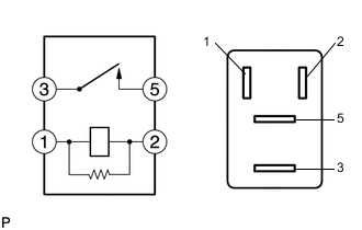
Measure the resistance according to the value(s) in the table below.
Standard Resistance Tester Connection Condition Specified Condition 3 - 5 Battery voltage not applied to terminals 1 and 2 10 kΩ or higher Battery voltage applied to terminals 1 and 2 Below 1 Ω
NG
REPLACE RELAY (ST/MGC RELAY)
OK
-
-
CHECK HARNESS AND CONNECTOR (ST/MGC RELAY - BODY GROUND)
-
Remove the ST/MGC relay from the No. 2 engine room relay block.
-
Measure the resistance according to the value(s) in the table below.
Standard Resistance Tester Connection Condition Specified Condition ST/MGC relay holder 1 - Body ground Always Below 1 Ω
NG
REPAIR OR REPLACE HARNESS OR CONNECTOR
OK
-
-
CHECK HARNESS AND CONNECTOR (ENGINE STOP AND START ECU - ST2 RELAY)
-
Disconnect the A58 ECM connector.
-
Disconnect the A73 engine stop and start ECU connector.
-
Remove the ST2 relay from the engine room relay block.
-
Measure the resistance according to the value(s) in the table below.
Standard Resistance Tester Connection Condition Specified Condition A73-23 (STA2) - ST2 relay holder 2 Always Below 1 Ω A73-23 (STA2) - Body ground Always 10 kΩ or higher ST2 relay holder 2 - Body ground Always 10 kΩ or higher
NG
REPAIR OR REPLACE HARNESS OR CONNECTOR
OK
-
-
INSPECT ST2 RELAY
-
Measure the resistance according to the value(s) in the table below.
Standard Resistance Tester Connection Condition Specified Condition 3 - 5 Battery voltage not applied to terminals 1 and 2 10 kΩ or higher Battery voltage applied to terminals 1 and 2 Below 1 Ω
NG
REPLACE RELAY (ST2 RELAY)
OK
-
-
CHECK HARNESS AND CONNECTOR (ST2 RELAY - BODY GROUND)
-
Remove the ST2 relay from the engine room relay block.
-
Measure the resistance according to the value(s) in the table below.
Standard Resistance Tester Connection Condition Specified Condition ST2 relay holder 1 - body ground Always Below 1 Ω
OK
REPLACE ENGINE STOP AND START ECU Click here
NG
REPAIR OR REPLACE HARNESS OR CONNECTOR
-