STOP AND START SYSTEM, Diagnostic DTC:P323B
| DTC Code | DTC Name |
|---|---|
| P323B | Backup Boost Converter |
DESCRIPTION
| DTC No. | DTC Detection Condition | Trouble Area |
|---|---|---|
| P323B | Any of the following conditions is met for 1 second or more (1trip detection logic):
|
|
-
After troubleshooting, perform the following steps to recheck for DTCs, check the battery voltage, and confirm that the Stop and Start system operates normally.
Tech Tips
-
If the battery terminal has been disconnected, the stop and start will be prohibited. In this case, drive the vehicle for 15 to 40 minutes to permit the stop and start operation.
-
Allow the engine to idle for 3 minutes after the engine warms up and check that the engine speed is within 50 rpm of the target idle speed.
-
Check if the battery has become weak.
-
Connect the GTS to the DLC3.
-
Clear the DTCs Click here.
-
Start the engine and warm it up.
-
Drive the vehicle at 7 km/h (4.3 mph) or more.
Note
When performing the confirmation driving pattern, obey all speed limits and traffic laws.
-
Stop the vehicle, allow the engine to stop due to stop and start system control and wait for 1 second or more (with the shift lever in D).
-
Release the brake pedal to allow the engine to restart (with the shift lever in D).
Tech Tips
If the engine cranks slowly when the engine is restarted, it can be determined that battery voltage is low.
-
Check that no DTCs are output Click here.
-
-
Check if the Stop and Start system operates normally.
Tech Tips
If the battery terminal has been disconnected, the stop and start will be prohibited. In this case, drive the vehicle for 15 to 40 minutes to permit the stop and start operation.
-
Warm up the engine.
-
Turn the air conditioning system off.
-
Drive the vehicle at 7 km/h (4.3 mph) or more.
Note
When performing the confirmation driving pattern, obey all speed limits and traffic laws.
-
Stop the vehicle, allow the engine to stop due to stop and start system control (with the shift lever in D).
-
Release the brake pedal to allow the engine to restart (with the shift lever in D).
Tech Tips
If the engine cranks slowly when the engine is restarted, it can be determined that battery voltage is low.
-
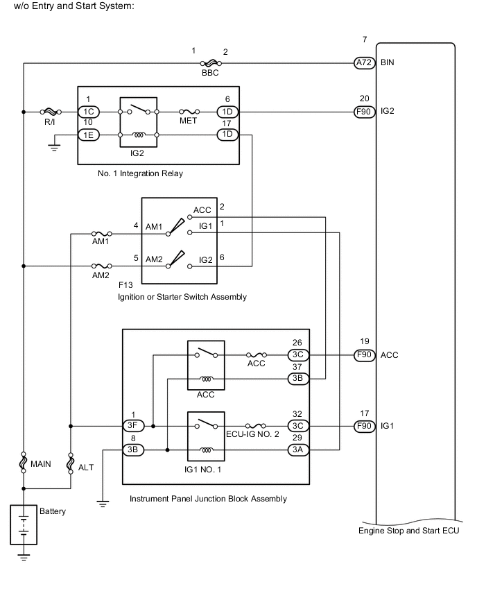
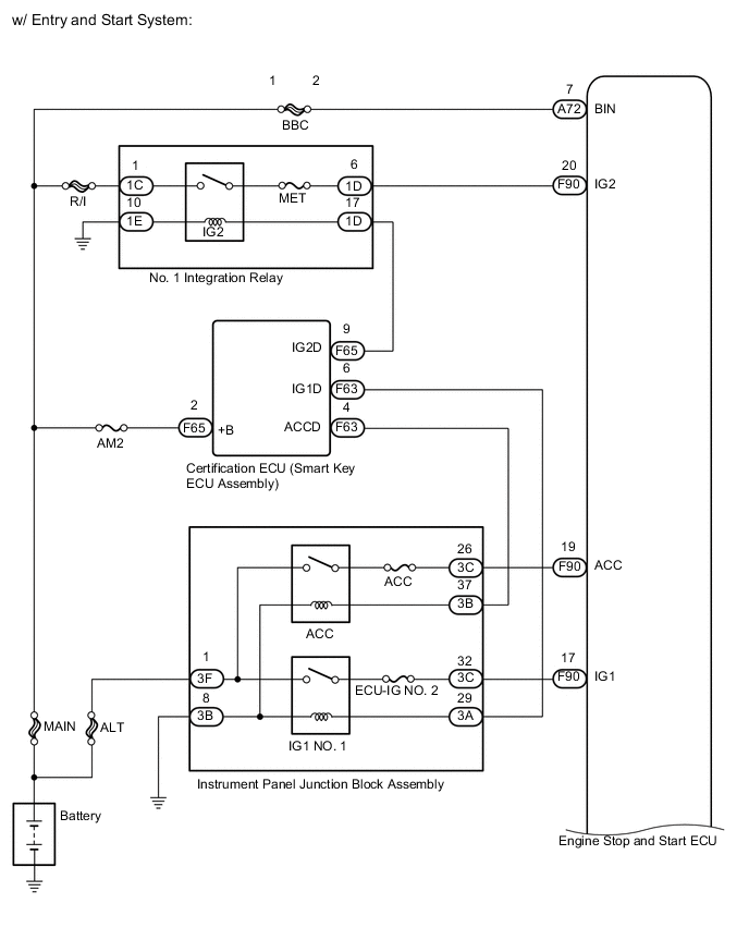
WIRING DIAGRAM
CAUTION / NOTICE / HINT
Note
-
If the engine stop and start ECU is being replaced, register the previously recorded number of starter operations into the new engine stop and start ECU Click here.
-
After the engine stop and start ECU is replaced or after an air conditioner kit is installed, clear the A/C information stored in the engine stop and start ECU Click here.
-
After the engine stop and start ECU or airbag sensor assembly (yaw rate sensor) is replaced, initialize and calibrate 0 point of deceleration sensor Click here.
-
Inspect the fuses for circuits related to this system before performing the following inspection procedure.
Tech Tips
Using the GTS, read the freeze frame data before troubleshooting. System condition information is recorded as freeze frame data the moment a DTC is stored. This information can be useful when troubleshooting.
PROCEDURE
-
CHECK HARNESS AND CONNECTOR (ENGINE STOP AND START ECU - ECM - BBC FUSE)
-
Disconnect the A72 engine stop and start ECU connector.
-
Remove the BBC fuse from engine room relay block.
-
Measure the resistance according to the value(s) in the table below.
Standard Resistance Tester Connection Condition Specified Condition A72-7 (BIN) - BBC fuse terminal 2 Always Below 1 Ω A72-7 (BIN) - Body ground Always 10 kΩ or higher BBC fuse terminal 2 - Body ground Always 10 kΩ or higher
NG 
REPAIR OR REPLACE HARNESS OR CONNECTOR
OK 
-
-
CHECK HARNESS AND CONNECTOR (ENGINE STOP AND START ECU POWER SOURCE CIRCUIT)
-
Disconnect the A72 or F90 engine stop and start ECU connector.
-
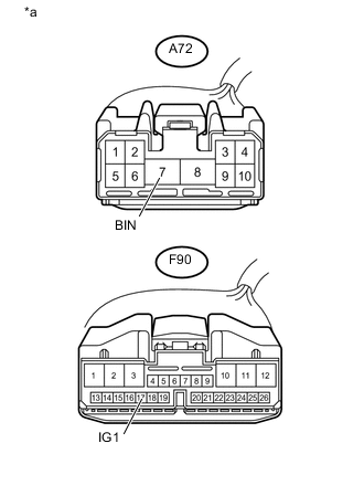
Text in Illustration *a Front view of wire harness connector:
(to Engine Stop and Start ECU)
Measure the voltage according to the value(s) in the table below.
Standard Voltage Tester Connection Condition Specified Condition A72-7 (BIN) - body ground Always 9.5 to 14 V -
Turn the ignition switch to ON.
-
Measure the voltage according to the value(s) in the table below.
Standard Voltage Tester Connection Condition Specified Condition F90-17 (IG1) - body ground Always 9.5 to 14 V
NG
REPAIR OR REPLACE HARNESS OR CONNECTOR
OK
-
-
CHECK HARNESS OR CONNECTOR (ENGINE STOP AND START ECU - BODY GROUND)
-
Disconnect the A73 engine stop and start ECU connector.
-
Measure the resistance according to the value(s) in the table below.
Standard Resistance Tester Connection Condition Specified Condition A73-17 (VB-) - Body ground Always Below 1 Ω
NG
REPAIR OR REPLACE HARNESS OR CONNECTOR
OK
-
-
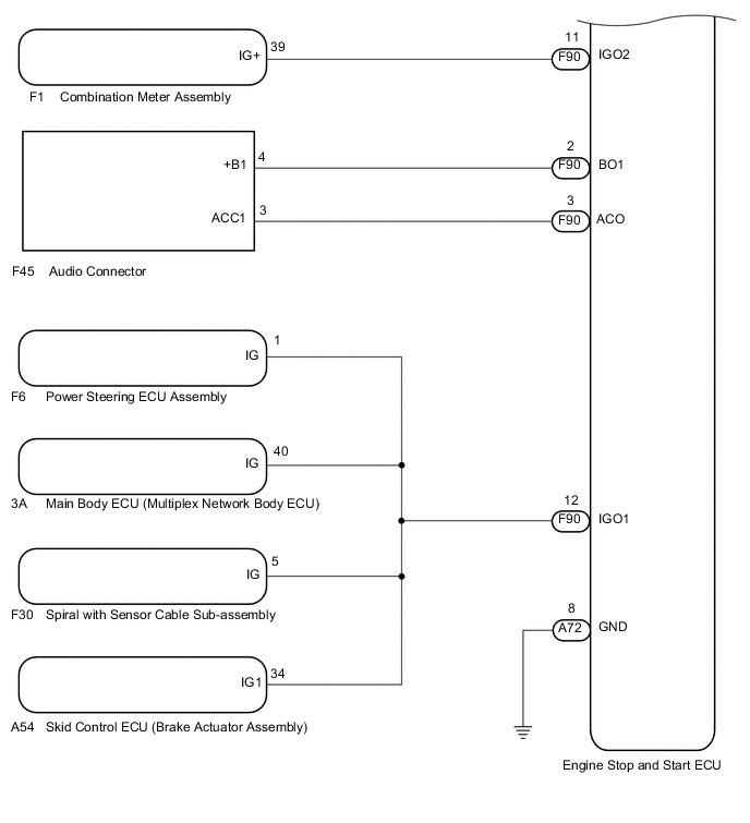
CHECK HARNESS OR CONNECTOR (ENGINE STOP AND START ECU - ECM - EACH ECU OR SENSOR)
-
Disconnect the F90 engine stop and start ECU connector.
-
Disconnect the F45 audio connector.
-
Disconnect the A54 skid control ECU (brake actuator assembly) connector.
-
Disconnect the F6 power steering ECU assembly connector.
-
Disconnect the 3A instrument panel junction block assembly (main body ECU (multiplex network body ECU)) connector.
-
Disconnect the F30 spiral with sensor cable sub-assembly connector.
-
Measure the resistance according to the value(s) in the table below.
Standard Resistance Tester Connection Condition Specified Condition F90-2 (BO1) - F45-4 (+B1) Always Below 1 Ω F90-12 (IGO1) - A54-34 (IG1) Always Below 1 Ω F90-12 (IGO1) - F6-1 (IG) Always Below 1 Ω F90-12 (IGO1) - 3A-40 (IG) Always Below 1 Ω F90-12 (IGO1) - F30-5 (IG) Always Below 1 Ω F90-2 (BO1) - Body ground Always 10 kΩ or higher F90-12 (IGO1) - Body ground Always 10 kΩ or higher
OK
REPLACE ENGINE STOP AND START ECU Click here
NG
REPAIR OR REPLACE HARNESS OR CONNECTOR
-