STOP AND START SYSTEM STA Signal Circuit
DESCRIPTION
The engine stop and start ECU utilizes the starter delay circuit to activate the start pinion activation relay (ST relay), then the starter motor activation relay (ST/ST2 relay), and then operates the starter.
CAUTION / NOTICE / HINT
CAUTION:
-
If the engine stop and start ECU is being replaced, register the previously recorded number of starter operations into the new engine stop and start ECU Click here.
-
After the engine stop and start ECU is replaced or after an air conditioner kit is installed, clear the A/C information stored in the engine stop and start ECU Click here.
-
After the engine stop and start ECU or airbag sensor assembly (yaw rate sensor) is replaced, initialize and calibrate 0 point of deceleration sensor Click here.
-
After the starter assembly is replaced, clear the number of starter operations. Click here
-
Inspect the fuses for circuits related to this system before performing the following inspection procedure.
Tech Tips
Using the GTS, read the freeze frame data before troubleshooting. System condition information is recorded as freeze frame data the moment a DTC is stored. This information can be useful when troubleshooting.
PROCEDURE
-
CHECK CRANKING OPERATION
-
Operate the ignition or starter switch, or push start switch to crank the engine.
Result Result Proceed to The engine cranks A The engine does not crank B
B 
PERFORM ACTIVE TEST USING GTS (Starter) Click here
A 
-
-
PERFORM ACTIVE TEST USING GTS (Starter)
-
Connect the GTS to the DLC3.
-
Turn the ignition switch to ON.
-
Turn the GTS on.
-
Enter the following menus: Powertrain / Stop and Start / Active Test / Starter.
-
When the starter is activated by Active Test, check whether the engine cranks.
Note
Starter operation in the Active Test stops automatically in 3 seconds.
OK The engine cranks
OK 
GO TO DTC CHART
NG
-
-
INSPECT ENGINE STOP AND START ECU
-
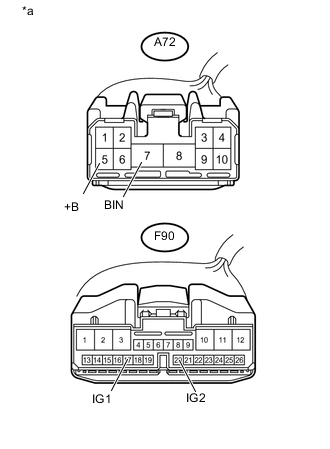
Disconnect the A72 and F90 engine stop and start ECU connectors.
-

Text in Illustration *a Front view of wire harness connector
(to Engine Stop and Start ECU)
Measure the voltage according to the value(s) in the table below.
Standard Voltage Tester Connection Condition Specified Condition A72-7 (BIN) - Body ground Always 9.5 to 14 V -
Turn the ignition switch to ON.
-
Measure the voltage according to the value(s) in the table below.
Standard Voltage Tester Connection Condition Specified Condition A72-5 (+B) - Body ground Ignition switch ON 9.5 to 14 V F90-17 (IG1) - Body ground Ignition switch ON 9.5 to 14 V F96-20 (IG2) - Body ground Ignition switch ON 9.5 to 14 V
NG
REPAIR OR REPLACE HARNESS AND CONNECTOR
OK
-
-
CHECK HARNESS AND CONNECTOR (ENGINE STOP AND START ECU - BODY GROUND)
-
Disconnect the A72 and A73 engine stop and start ECU connectors.
-
Measure the resistance according to the value(s) in the table below.
Standard Resistance Tester Connection Condition Specified Condition A72-8 (GND) - Body ground Always Below 1 Ω A73-17 (VB-) - Body ground Always Below 1 Ω
OK
REPLACE ENGINE STOP AND START ECU Click here
NG
REPAIR OR REPLACE HARNESS AND CONNECTOR
-
-
PERFORM ACTIVE TEST USING GTS (Starter)
-
Connect the GTS to the DLC3.
-
Turn the ignition switch to ON.
-
Turn the GTS on.
-
Enter the following menus: Powertrain / Stop and Start / Active Test / Starter.
-
When the starter is activated by Active Test, check whether the engine cranks.
Note
Starter operation in the Active Test stops automatically in 3 seconds.
OK The engine cranks
NG
INSPECT ENGINE STOP AND START ECU Click here
OK
-
-
READ VALUE USING GTS (NEUTRAL SWITCH)
-
Connect the GTS to the DLC3.
-
Turn the ignition switch to ON.
-
Turn the GTS on.
-
Enter the following menus: Powertrain / Stop and Start / Data List / Neutral Switch.
-
Read the Data Monitor when the shift lever is operated
OK Tester Display Measurement Item/Range Normal Condition Diagnostic Note Neutral Switch Displays the shift position N or P /
Displays ON or OFF
ON: Shift lever is in N or P
OFF: Shift lever is in other than N or P
- Result Result Proceed to Data Monitor display is not within standards A Data Monitor display is within standards
( w/o Entry and Start System)
B Data Monitor display is within standards
( w/ Entry and Start System)
C
B
INSPECT IGNITION OR START SWITCH ASSEMBLY Click here
C
CHECK HARNESS AND CONNECTOR (CERTIFICATION ECU (SMART KEY ECU ASSEMBLY) - ENGINE STOP AND START ECU) Click here
A
-
-
INSPECT PARK/NEUTRAL POSITION SWITCH ASSEMBLY
-
Inspect the park/neutral position switch assembly Click here.
Result Result Proceed to OK
(w/o Entry and Start System)
A OK
( w/ Entry and Start System)
B NG C
B
CHECK HARNESS AND CONNECTOR (CERTIFICATION ECU (SMART KEY ECU ASSEMBLY) - ENGINE STOP AND START ECU) Click here
C
REPLACE PARK/NEUTRAL POSITION SWITCH ASSEMBLY Click here
A
-
-
CHECK HARNESS AND CONNECTOR (IGNITION OR START SWITCH ASSEMBLY - ST RELAY)
-
Disconnect the F13 ignition or start switch assembly connector.
-
Remove the ST relay from No. 2 engine room relay block.
-
Measure the resistance according to the value(s) in the table below.
Standard Resistance Tester Connection Condition Specified Condition F13-7 (ST2) - ST relay holder 2 Shift lever is in N or P Below 1 Ω F13-7 (ST2) - ST relay holder 2 Shift lever is in other than N or P 10 kΩ or more
OK
USE SIMULATION METHOD TO CHECK Click here
NG
REPAIR OR REPLACE HARNESS AND CONNECTOR
-
-
INSPECT IGNITION OR START SWITCH ASSEMBLY
-
Inspect the ignition or start switch assembly Click here.
NG
REPLACE IGNITION OR START SWITCH ASSEMBLY
OK
-
-
CHECK HARNESS AND CONNECTOR (IGNITION OR START SWITCH ASSEMBLY - BATTERY)
-
Disconnect the F13 ignition or start switch assembly connector.
-
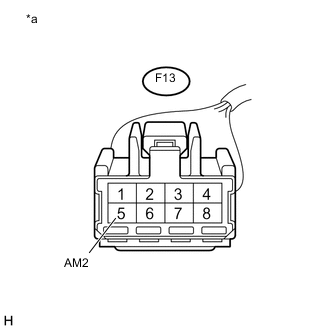
Text in Illustration *a Front view of wire harness connector
(to Ignition Switch or Start Switch Assembly)
Measure the voltage according to the value(s) in the table below.
Standard Voltage Tester Connection Condition Specified Condition F13-5 (AM2) - Body ground Always 9.5 to 14 V
NG
REPAIR OR REPLACE HARNESS AND CONNECTOR
OK
-
-
CHECK HARNESS AND CONNECTOR (IGNITION OR START SWITCH ASSEMBLY - PARK/NEUTRAL POSITION SWITCH)
-
Disconnect the F13 ignition or start switch assembly connector.
-
Disconnect the B69 park/neutral position switch connector.
-
Measure the resistance according to the value(s) in the table below.
Standard Resistance Tester Connection Condition Specified Condition F13-7 (ST2) - B69-4 (B) Always Below 1 Ω F13-7 (ST2) or B69-4 (B) - body ground Always 10 kΩ or more
OK
USE SIMULATION METHOD TO CHECK Click here
NG
REPAIR OR REPLACE HARNESS AND CONNECTOR
-
-
CHECK HARNESS AND CONNECTOR (CERTIFICATION ECU (SMART KEY ECU ASSEMBLY) - ENGINE STOP AND START ECU)
-
Disconnect the B69 park/neutral position switch connector.
-
Disconnect the F65 certification ECU (smart key ECU assembly) connector.
-
Disconnect the A73 engine stop and start ECU connector.
-
Measure the resistance according to the value(s) in the table below.
Standard Resistance Tester Connection Condition Specified Condition F65-5 (STAR) - A73-28 (CLL) Always Below 1 Ω F65-5 (STAR) or A73-28 (CLL) - body ground Always 10 kΩ or more
NG
REPAIR OR REPLACE HARNESS AND CONNECTOR
OK
-
-
CHECK HARNESS AND CONNECTOR (ENGINE STOP AND START ECU - BATTERY)
-
Disconnect the A73 engine stop and start ECU connector.
-
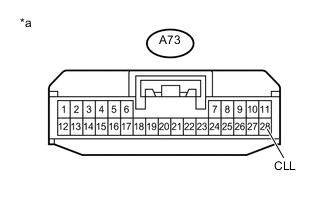
Text in Illustration *a Front view of wire harness connector
(to Engine Stop and Start ECU)
Measure the voltage according to the value(s) in the table below.
Standard Voltage Tester Connection Condition Specified Condition A73-28 (CLL) - Body ground Engine start operation (when the push start switch is pushed) due to the use of the push start switch 9.5 to 14 V
OK
USE SIMULATION METHOD TO CHECK Click here
NG
GO TO ENTRY AND START SYSTEM Click here
-
-
CHECK HARNESS AND CONNECTOR (CERTIFICATION ECU (SMART KEY ECU ASSEMBLY) - ENGINE STOP AND START ECU)
-
Remove the ST relay from No. 2 engine room relay block.
-
Disconnect the F65 certification ECU (smart key ECU assembly) connector.
-
Measure the resistance according to the value(s) in the table below.
Standard Resistance Tester Connection Condition Specified Condition F65-5 (STAR) - ST relay holder 2 Shift lever is in N or P Below 1 Ω F65-5 (STAR) - ST relay holder 2 Shift lever is in other than N or P 10 kΩ or more
OK
USE SIMULATION METHOD TO CHECK Click here
NG
REPAIR OR REPLACE HARNESS AND CONNECTOR
-
-
INSPECT ENGINE STOP AND START ECU
-
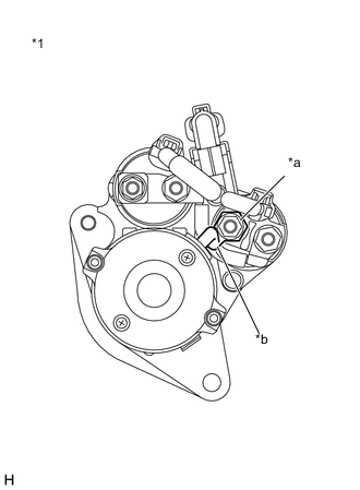
Connect an oscilloscope to the STA, STA2 and GND terminals of the engine stop and start ECU connector.
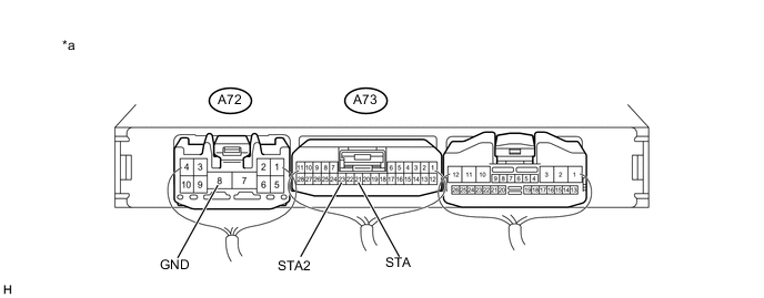
Text In Illustration *a Component with harness connected:
(Engine Stop and Start ECU)
- - -
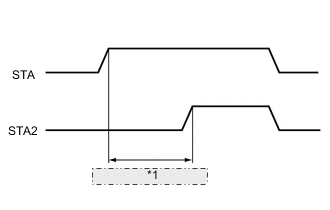
*1 0.03 to 0.06 seconds Check the waveform immediately after starting
Item Condition Tester connection STA - GND
STA2 - GND
Condition Engine starting by operating the ignition or starter switch assembly, or pushing the push start switch Result Tester Connection Condition Specified Condition Proceed to A73-21 (STA) - A72-8 (GND)
A73-23 (STA2) - A72-8 (GND)
Engine starting by operating the ignition or starter switch assembly, or pushing the push start switch Time from ST relay on to ST2 relay on is within a 0.03 to 0.06 second frame A Time from ST relay on to ST2 relay on is not within a 0.03 to 0.06 second frame B ST relay turns on but ST2 relay remains off C Both ST relay and ST2 relay remain off D Note
After replacing the engine stop and start ECU, check that there is no malfunction in the ring gear or starter pinion. Malfunctions in the delay circuit may cause wear in the ring gear or starter pinion.
B
REPLACE ENGINE STOP AND START ECU Click here
C
INSPECT ENGINE STOP AND START ECU Click here
D
CHECK HARNESS AND CONNECTOR (ST RELAY - BODY GROUND) Click here
A
-
-
INSPECT RELAY (ST, ST2 RELAY)
-
Inspect the ST relay Click here.
-
Inspect the ST2 relay Click here.
NG
REPLACE RELAY (ST, ST2 RELAY)
OK
-
-
CHECK HARNESS AND CONNECTOR (ST, ST2 RELAY - BATTERY)
-
Remove the ST relay from No. 2 engine room relay block.
-
Remove the ST2 relay from engine room relay block.
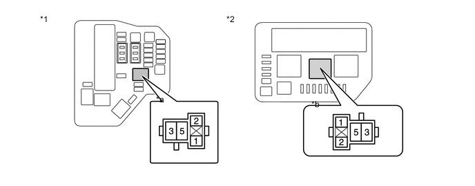
Text in Illustration *1 Engine Room Relay Block *2 No. 2 Engine Room Relay Block *a ST2 Relay Holder *b ST Relay Holder -
Measure the voltage according to the value(s) in the table below.
Standard Voltage Tester Connection Condition Specified Condition ST relay holder 5 - body ground Always 9.5 to 14 V ST2 relay holder 5 - body ground Always 9.5 to 14 V
NG
REPAIR OR REPLACE HARNESS AND CONNECTOR
OK
-
-
CHECK HARNESS AND CONNECTOR (ST, ST2 RELAY - STARTER)
-
Remove the ST relay from No. 2 engine room relay block.
-
Remove the ST2 relay from engine room relay block.
-
Disconnect the B87 engine stop and start ECU.
-
Measure the resistance according to the value(s) in the table below.
Standard Resistance Tester Connection Condition Specified Condition ST relay holder 3 - B87-2 Always Below 1 Ω ST2 relay holder 3 - B87-1 Always Below 1 Ω
NG
REPAIR OR REPLACE HARNESS AND CONNECTOR
OK
-
-
CHECK HARNESS AND CONNECTOR (ST RELAY - BODY GROUND)
-
Remove the ST relay from No. 2 engine room relay block.
-
Measure the resistance according to the value(s) in the table below.
Standard Resistance Tester Connection Condition Specified Condition ST relay holder 1 - body ground Always Below 1 Ω
NG
REPAIR OR REPLACE HARNESS AND CONNECTOR
OK
-
-
CHECK HARNESS AND CONNECTOR (ST2 RELAY - BODY GROUND)
-
Remove the ST2 relay from engine room relay block.
-
Measure the resistance according to the value(s) in the table below.
Standard Resistance Tester Connection Condition Specified Condition ST2 relay holder 1 - Body ground Always Below 1 Ω
NG
REPAIR OR REPLACE HARNESS AND CONNECTOR
OK
-
-
CHECK HARNESS AND CONNECTOR (ENGINE STOP AND START ECU - ST RELAY)
-
Disconnect the F65 certification ECU (smart key ECU assembly) connector.
-
Disconnect the B69 park/neutral position switch connector.
-
Disconnect the A73 engine stop and start ECU.
-
Remove the ST relay from No. 2 engine room relay block.
-
Measure the resistance according to the value(s) in the table below.
Standard Resistance Tester Connection Condition Specified Condition A73-21 (STA) - ST relay holder 2 Always Below 1 Ω A73-21 (STA) - Body ground Always 10 kΩ or higher ST relay holder 2 - Body ground Always 10 kΩ or higher
NG
REPAIR OR REPLACE HARNESS AND CONNECTOR
OK
-
-
CHECK HARNESS AND CONNECTOR (ENGINE STOP AND START ECU - ST2 RELAY)
-
Disconnect the A58 ECM connector.
-
Disconnect the A73 engine stop and start ECU.
-
Remove the ST2 relay from engine room relay block.
-
Measure the resistance according to the value(s) in the table below.
Standard Resistance Tester Connection Condition Specified Condition A73-23 (STA2) - ST2 relay holder 2 Always Below 1 Ω A73-23 (STA2) - Body ground Always 10 kΩ or higher ST2 relay holder 2 - Body ground Always 10 kΩ or higher
NG
REPAIR OR REPLACE HARNESS AND CONNECTOR
OK
-
-
CHECK STARTER OPERATION
-
Connect the GTS to the DLC3.
-
Turn the ignition switch to ON.
-
Turn the GTS on.
-
Enter the following menus: Powertrain / Stop and Start / Active Test / Starter Motor Drive Magnet Switch.
-
Connect the oscilloscope positive probe to the positive (+) terminal on the battery, and the negative probe to the negative (-) terminal on the battery.
-
Read the number of drops in the waveform when the Starter Motor of the Active Test is performed.
Note
-
Starter motor operation during the Active Test stops automatically in 3 seconds.
-
Do not force the starter pinion to operate.
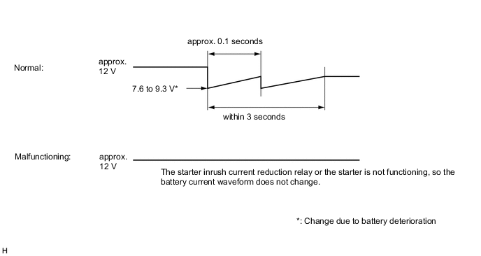
OK There are 2 drops from approximately 12 V in waveform Result Number of drops in waveform Proceed to No change from approximately 12 V A 2 drops from approximately 12 V in waveform B -
B
INSPECT STARTER ASSEMBLY Click here
A
-
-
INSPECT STARTER INRUSH CURRENT REDUCTION RELAY
-
Disconnect cable from negative battery terminal.
-
Disconnect B and M starter inrush current reduction relay terminal.
-
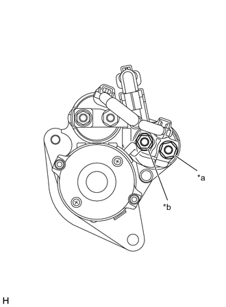
Text in Illustration *1 Starter Assembly *a B terminal *b M terminal Measure the resistance according to the value(s) in the table below.
Standard Resistance Tester Connection Condition Specified Condition B terminal - M terminal Always Below 1 Ω
NG
INSPECT STARTER ASSEMBLY (M TERMINAL) Click here
OK
-
-
INSPECT STARTER ASSEMBLY (C TERMINAL)
-
Disconnect cable from negative battery terminal.
-
Disconnect B starter inrush current reduction relay terminal.
-
Disconnect C starter assembly terminal.
-
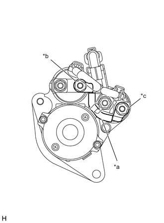
Text in Illustration *1 Starter Assembly *a Check Part *b C terminal *c B terminal Measure the resistance according to the value(s) in the table below.
Standard Resistance Tester Connection Condition Specified Condition C terminal - M terminal Always Below 1 Ω
OK
REPLACE STARTER ASSEMBLY Click here
NG
REPAIR OR REPLACE HARNESS AND CONNECTOR
-
-
INSPECT STARTER ASSEMBLY (M TERMINAL)
-
Disconnect cable from negative battery terminal.
-
Disconnect M starter inrush current reduction relay terminal.
-
Text in Illustration *1 Starter Assembly *a Check Part *b M terminal Measure the resistance according to the value(s) in the table below.
Standard Resistance Tester Connection Condition Specified Condition M terminal - Body ground Always Below 1 Ω
OK
REPLACE STARTER INRUSH CURRENT REDUCTION RELAY
NG
REPLACE STARTER ASSEMBLY Click here
-
-
INSPECT STARTER ASSEMBLY
-
Inspect the starter assembly Click here.
OK
USE SIMULATION METHOD TO CHECK Click here
NG
REPLACE STARTER ASSEMBLY Click here
-
-
INSPECT ENGINE STOP AND START ECU
-
Disconnect the A72 and F90 engine stop and start ECU connectors.
-
Text in Illustration *a Front view of wire harness connector
(to Engine Stop and Start ECU)
Measure the voltage according to the value(s) in the table below.
Standard Voltage Tester Connection Condition Specified Condition A72-7 (BIN) - Body ground Always 9.5 to 14 V -
Turn the ignition switch to ON.
-
Measure the voltage according to the value(s) in the table below.
Standard Voltage Tester Connection Condition Specified Condition A72-5 (+B) - Body ground Ignition switch ON 9.5 to 14 V F90-17 (IG1) - Body ground Ignition switch ON 9.5 to 14 V F90-20 (IG2) - Body ground Ignition switch ON 9.5 to 14 V
NG
REPAIR OR REPLACE HARNESS AND CONNECTOR
OK
-
-
CHECK HARNESS AND CONNECTOR (ENGINE STOP AND START ECU - BODY GROUND)
-
Disconnect the A72 and A73 engine stop and start ECU connectors.
-
Measure the resistance according to the value(s) in the table below.
Standard Resistance Tester Connection Condition Specified Condition A72-8 (GND) - Body ground Always Below 1 Ω A73-17 (VB-) - Body ground Always Below 1 Ω
OK
REPLACE ENGINE STOP AND START ECU Click here
NG
REPAIR OR REPLACE HARNESS AND CONNECTOR
-