LIGHTING SYSTEM Hazard Warning Switch Circuit
DESCRIPTION
The combination meter assembly receives information signals from the hazard warning signal switch assembly, and blinks the turn signal lights.
WIRING DIAGRAM
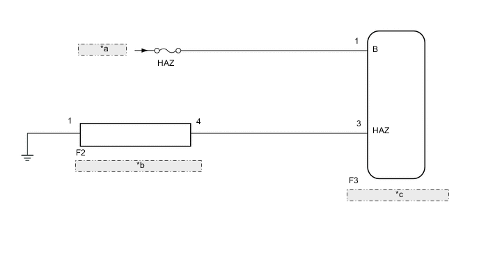
| *a | from Battery |
| *b | HAZARD WARNING SIGNAL SWITCH ASSEMBLY |
| *c | COMBINATION METER ASSEMBLY |
PROCEDURE
-
READ VALUE USING INTELLIGENT TESTER (HEADLIGHT DIMMER SWITCH)
-
Using the intelligent tester, read the Data List Click here.
Meter Tester Display Measurement Item/Range Normal Condition Diagnostic Note Hazard Flasher Switch Hazard warning signal switch signal / ON or OFF ON: Hazard warning signal switch on
OFF: Hazard warning signal switch off
- OK The display is as specified in the normal condition column. Result Result Proceed to NG A OK B
B 
CHECK HARNESS AND CONNECTOR (BATTERY - COMBINATION METER) Click here
A 
-
-
INSPECT HAZARD WARNING SIGNAL SWITCH ASSEMBLY
-
Remove the hazard warning signal switch assembly Click here.
-
Inspect the hazard warning signal switch assembly Click here.
NG 
REPLACE HAZARD WARNING SIGNAL SWITCH ASSEMBLY Click here
OK
-
-
CHECK HARNESS AND CONNECTOR (HAZARD WARNING SIGNAL SWITCH - COMBINATION METER)
-
Remove the combination meter assembly Click here.
-
Measure the resistance according to the value(s) in the table below.
Standard Resistance (Check for Open) Tester Connection Condition Specified Condition F2-4 - F3-3 (HAZ) Always Below 1 Ω F2-1 - Body Ground Always Below 1 Ω Standard Resistance (Check for Short) Tester Connection Condition Specified Condition F2-4 - Body ground Always 10 kΩ or higher
NG
REPAIR OR REPLACE HARNESS OR CONNECTOR
OK
-
-
CHECK HARNESS AND CONNECTOR (BATTERY - COMBINATION METER)
-
Measure the voltage according to the value(s) in the table below.
Standard Voltage Tester Connection Condition Specified Condition F3-1 - Body Ground Always 11 to 14 V
OK
REPLACE COMBINATION METER ASSEMBLY Click here
NG
REPAIR OR REPLACE HARNESS OR CONNECTOR
-