LIGHTING SYSTEM Headlight Dimmer Switch Circuit
DESCRIPTION
The main body ECU (multiplex network body ECU) receives the following signals:
-
Headlight dimmer switch tail, head, AUTO*, high or high flash signal
-
Front fog light switch signal
-
Rear fog light switch signal
-
*: w/ Automatic Light Control System
The combination meter assembly receives the following signals:
-
Turn signal switch turn right or turn left signal
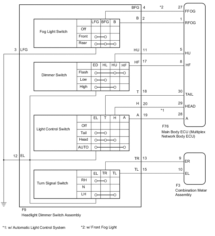
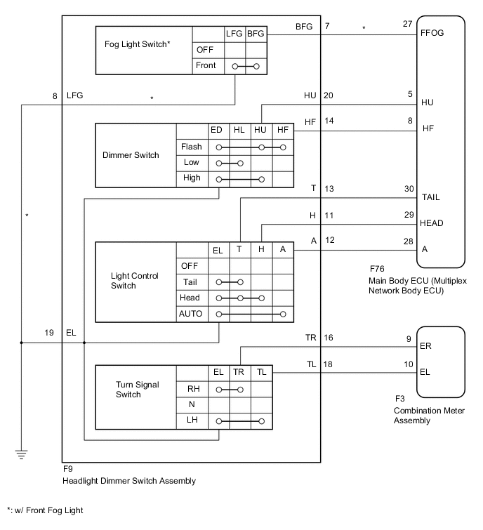
WIRING DIAGRAM
-
w/ Rear Fog Light
-
w/o Rear Fog Light
CAUTION / NOTICE / HINT
Note
Initialization is necessary when the main body ECU (multiplex network body ECU) is replaced Click here.*
-
*: w/ Automatic Light Control System
PROCEDURE
-
READ VALUE USING INTELLIGENT TESTER (HEADLIGHT DIMMER SWITCH)
-
Using the intelligent tester, read the Data List Click here.
Main Body Tester Display Measurement Item/Range Normal Condition Diagnostic Note Dimmer SW Dimmer switch high position signal / ON or OFF ON: Dimmer switch in high position
OFF: Dimmer switch not in high position
- Passing Light SW Dimmer switch high flash signal / ON or OFF ON: Dimmer switch in high flash position
OFF: Dimmer switch not in high flash position
- Rear Fog Light SW Rear fog light switch signal / ON or OFF ON: Rear fog light switch on
OFF: Rear fog light switch off
- Front Fog Light SW Front fog light switch signal / ON or OFF ON: Front fog light switch on
OFF: Front fog light switch off
- Auto Light SW Light control switch AUTO signal / ON or OFF ON: Light control switch in AUTO position
OFF: Light control switch not in AUTO position
- Head Light SW (Head) Light control switch HEAD signal / ON or OFF ON: Light control switch in HEAD position
OFF: Light control switch not in HEAD position
- Head Light SW (Tail) Light control switch TAIL signal / ON or OFF ON: Light control switch in TAIL or HEAD position
OFF: Light control switch not in TAIL or HEAD position
- Combination Meter Tester Display Measurement Item/Range Normal Condition Diagnostic Note Turn Signal Switch (Right) Turn signal switch signal (turn right) / ON or OFF ON: Turn signal switch right on (turn right)
OFF: Turn signal switch neutral
- Turn Signal Switch (Left) Turn signal switch signal (turn left) / ON or OFF ON: Turn signal switch left on (turn left)
OFF: Turn signal switch neutral
- OK The display is as specified in the normal condition column. Result Result Proceed to NG (Light control switch, dimmer switch or fog light switch) A NG (Turn signal switch) B OK C
B 
INSPECT HEADLIGHT DIMMER SWITCH ASSEMBLY Click here
C 
PROCEED TO NEXT SUSPECTED AREA SHOWN IN PROBLEM SYMPTOMS TABLE Click here
A 
-
-
INSPECT HEADLIGHT DIMMER SWITCH ASSEMBLY
-
Remove the headlight dimmer switch assembly Click here.
-
Inspect the headlight dimmer switch assembly Click here.
NG
REPLACE HEADLIGHT DIMMER SWITCH ASSEMBLY Click here
OK
-
-
CHECK HARNESS AND CONNECTOR (HEADLIGHT DIMMER SWITCH - MAIN BODY ECU, BODY GROUND)
-
Disconnect the F9 headlight dimmer switch assembly connector.
-
Disconnect the F76 main body ECU (multiplex network body ECU) connector.
-
Measure the resistance according to the value(s) in the table below.
Standard Resistance (Check for Open) w/ Rear Fog Light Tester Connection Condition Specified Condition F9-2 (B) - F76-1 (RFOG) Always Below 1 Ω F9-4 (BFG) - F76-27 (FFOG)*1 Always Below 1 Ω F9-11 (HU) - F76-5 (HU) Always Below 1 Ω F9-17 (HF) - F76-8 (HF) Always Below 1 Ω F9-18 (T) - F76-30 (TAIL) Always Below 1 Ω F9-19 (A) - F76-28 (A)*2 Always Below 1 Ω F9-20 (H) - F76-29 (HEAD) Always Below 1 Ω F9-3 (LFG) - Body ground Always Below 1 Ω F9-12 (EL) - Body ground Always Below 1 Ω w/o Rear Fog Light Tester Connection Condition Specified Condition F9-7 (BFG) - F76-27 (FFOG)*1 Always Below 1 Ω F9-20 (HU) - F76-5 (HU) Always Below 1 Ω F9-14 (HF) - F76-8 (HF) Always Below 1 Ω F9-13 (T) - F76-30 (TAIL) Always Below 1 Ω F9-12 (A) - F76-28 (A)*2 Always Below 1 Ω F9-11 (H) - F76-29 (HEAD) Always Below 1 Ω F9-8 (LFG) - Body ground*1 Always Below 1 Ω F9-19 (EL) - Body ground Always Below 1 Ω
-
*1: w/ Front Fog Light
-
*2: w/ Automatic Light Control System
Standard Resistance (Check for Short) w/ Rear Fog Light Tester Connection Condition Specified Condition F9-2 (B) - Body ground Always 10 kΩ or higher F9-4 (BFG) - Body ground*1 Always 10 kΩ or higher F9-11 (HU) - Body ground Always 10 kΩ or higher F9-17 (HF) - Body ground Always 10 kΩ or higher F9-18 (T) - Body ground Always 10 kΩ or higher F9-19 (A) - Body ground*2 Always 10 kΩ or higher F9-20 (H) - Body ground Always 10 kΩ or higher w/o Rear Fog Light Tester Connection Condition Specified Condition F9-7 (BFG) - Body ground*1 Always 10 kΩ or higher F9-20 (HU) - Body ground Always 10 kΩ or higher F9-14 (HF) - Body ground Always 10 kΩ or higher F9-13 (T) - Body ground Always 10 kΩ or higher F9-12 (A) - Body ground*2 Always 10 kΩ or higher F9-11 (H) - Body ground Always 10 kΩ or higher
-
*1: w/ Front Fog Light
-
*2: w/ Automatic Light Control System
-
OK
REPLACE MAIN BODY ECU (MULTIPLEX NETWORK BODY ECU) Click here
NG
REPAIR OR REPLACE HARNESS OR CONNECTOR
-
-
INSPECT HEADLIGHT DIMMER SWITCH ASSEMBLY
-
Remove the headlight dimmer switch assembly Click here.
-
Inspect the headlight dimmer switch assembly Click here.
NG
REPLACE HEADLIGHT DIMMER SWITCH ASSEMBLY Click here
OK
-
-
CHECK HARNESS AND CONNECTOR (HEADLIGHT DIMMER SWITCH - COMBINATION METER, BODY GROUND)
-
Disconnect the F9 headlight dimmer switch assembly connector.
-
Disconnect the F3 combination meter assembly connector.
-
Measure the resistance according to the value(s) in the table below.
Standard Resistance (Check for Open) w/ Rear Fog Light Tester Connection Condition Specified Condition F9-13 (TR) - F3-9 (ER) Always Below 1 Ω F9-15 (TL) - F3-10 (EL) Always Below 1 Ω F9-12 (EL) - Body ground Always Below 1 Ω w/o Rear Fog Light Tester Connection Condition Specified Condition F9-16 (TR) - F3-9 (ER) Always Below 1 Ω F9-18 (TL) - F3-10 (EL) Always Below 1 Ω F9-19 (EL) - Body ground Always Below 1 Ω Standard Resistance (Check for Short) w/ Rear Fog Light Tester Connection Condition Specified Condition F9-13 (TR) - Body ground Always 10 kΩ or higher F9-15 (TL) - Body ground Always 10 kΩ or higher w/o Rear Fog Light Tester Connection Condition Specified Condition F9-16 (TR) - Body ground Always 10 kΩ or higher F9-18 (TL) - Body ground Always 10 kΩ or higher
OK
REPLACE COMBINATION METER ASSEMBLY Click here
NG
REPAIR OR REPLACE HARNESS OR CONNECTOR
-