AIR CONDITIONING SYSTEM Steering Pad Switch Circuit
DESCRIPTION
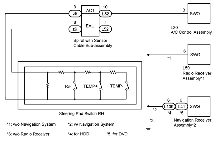
The R/F, TEMP UP (+), and TEMP DOWN (-) switches are located on the steering pad switch RH. The resistance of the steering pad switch RH changes in accordance with switch operation. The A/C control assembly outputs voltage to the steering pad switch RH and reads voltage changes due to the resistance changes that result from switch operation.
Tech Tips
If there is an open in the circuit, the A/C system cannot be operated by the steering pad switch RH.
If there is a short in the circuit, the resulting condition is the same as if the switch were continuously depressed. Therefore, the A/C control assembly cannot be operated by the steering pad switch RH, and the A/C control assembly will not be able to function correctly.
WIRING DIAGRAM
INSPECTION PROCEDURE
Note
The vehicle is equipped with an SRS (Supplemental Restraint System). Before servicing (including removal or installation of parts), be sure to read the precaution for Supplemental Restraint System Click here.
PROCEDURE
-
INSPECT A/C CONTROL ASSEMBLY
-
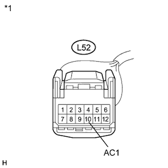
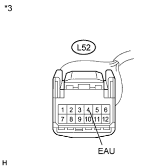
Text in Illustration *1 Front view of wire harness connector
(to Spiral with Sensor Cable Sub-assembly)
Disconnect the connector from the spiral with sensor cable sub-assembly.
-
Measure the voltage according to the value(s) in the table below.
Standard Voltage Tester Connection Condition Specified Condition L52-10 (AC1) - Body ground Power switch off Below 1 V L52-10 (AC1) - Body ground Power switch on (IG) 4.5 to 5.5 V
NG 
CHECK HARNESS AND CONNECTOR (A/C CONTROL ASSEMBLY - SPIRAL WITH SENSOR CABLE SUB-ASSEMBLY) Click here
OK 
-
-
CHECK HARNESS AND CONNECTOR
-
Disconnect the connector from the navigation receiver assembly.
-
Disconnect the connector from the radio receiver assembly.
-
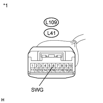
Text in Illustration *1 Front view of wire harness connector
(to Navigation Receiver Assembly)
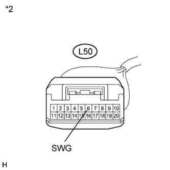
*2 Front view of wire harness connector
(to Radio Receiver Assembly)
*3 Front view of wire harness connector
(to Spiral with Sensor Cable Sub-assembly)
Measure the resistance according value(s) in the table below.
Standard Resistance Tester Connection Condition Specified Condition L109-6 (SWG) - L52-4 (EAU)*4 Always Below 1 Ω L41-6 (SWG) - L52-4 (EAU)*5 Always Below 1 Ω L50-6 (SWG) - L52-4 (EAU)*6 Always Below 1 Ω L52-4 (EAU) - Body ground*7 Always Below 1 Ω L109-6 (SWG) - Body ground*4 Always 10 kΩ or higher L41-6 (SWG) - Body ground*5 Always 10 kΩ or higher L50-6 (SWG) - Body ground*6 Always 10 kΩ or higher
-
*4: w/ Navigation System (for HDD)
-
*5: w/ Navigation System (for DVD)
-
*6: w/o Navigation System
-
*7: w/o Radio Receiver
-
NG 
REPAIR OR REPLACE HARNESS OR CONNECTOR
OK
-
-
INSPECT STEERING PAD SWITCH RH
-
Disconnect the connector from the steering pad switch RH.
-
Measure the resistance according to the value(s) in the table below.
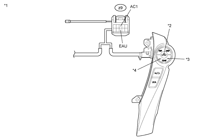
Standard Resistance Tester Connection Condition Specified Condition z9-3 (AC1) - z9-8 (EAU) No switch pushed 95 to 105 kΩ z9-3 (AC1) - z9-8 (EAU) R/F switch pushed 312 to 345 Ω z9-3 (AC1) - z9-8 (EAU) TEMP+ switch pushed 950 to 1050 Ω z9-3 (AC1) - z9-8 (EAU) TEMP- switch pushed 2954 to 3265 Ω Text in Illustration *1 Component without harness connected
(Steering Pad Switch RH)
*2 R/F Switch *3 TEMP+ Switch *4 TEMP- Switch
NG
REPLACE STEERING PAD SWITCH RH Click here
OK
-
-
INSPECT SPIRAL WITH SENSOR CABLE SUB-ASSEMBLY
-
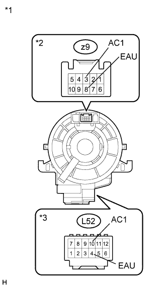
Text in Illustration *1 Component without harness connected
(Spiral with Sensor Cable Sub-assembly)
*2 Steering Pad Switch Side *3 Vehicle Side Disconnect the connector from the spiral with sensor cable sub-assembly.
-
Measure the resistance according to the value(s) in the table below.
Standard Resistance Tester Connection Condition Specified Condition L52-10 (AC1) - z9-3 (AC1) Center Below 1 Ω 2.5 rotations to the left 2.5 rotations to the right L52-4 (EAU) - z9-8 (EAU) Center Below 1 Ω 2.5 rotations to the left 2.5 rotations to the right Note
The spiral with sensor cable sub-assembly is an important part of the SRS airbag system. Incorrect removal or installation of the spiral with sensor cable sub-assembly may prevent the airbag from deploying. Refer to the pages shown in the brackets.
Tech Tips
-
Removal Click here
-
Installation Click here
-
The spiral cable makes a maximum of approximately 5 rotations.
-
NG
REPLACE SPIRAL WITH SENSOR CABLE SUB-ASSEMBLY Click here
OK
-
-
CONFIRM MODEL
Result Result Proceed to w/ Navigation System A w/o Navigation System B w/o Radio Receiver C
B
REPLACE RADIO RECEIVER ASSEMBLY Click here
C
PROCEED TO NEXT SUSPECTED AREA SHOWN IN PROBLEM SYMPTOMS TABLE Click here
A
-
REPLACE NAVIGATION RECEIVER ASSEMBLY
-
Replace the navigation receiver assembly with a known good one and check if the same problem occurs again Click here.
OK Same problem does not occur.
NG
PROCEED TO NEXT SUSPECTED AREA SHOWN IN PROBLEM SYMPTOMS TABLE Click here
OK 
END (NAVIGATION RECEIVER ASSEMBLY WAS DEFECTIVE)
-
-
REPLACE RADIO RECEIVER ASSEMBLY
-
Replace the radio receiver assembly with a known good one and check if the same problem occurs again Click here.
OK Same problem does not occur.
NG
PROCEED TO NEXT SUSPECTED AREA SHOWN IN PROBLEM SYMPTOMS TABLE Click here
OK
END (RADIO RECEIVER ASSEMBLY WAS DEFECTIVE)
-
-
CHECK HARNESS AND CONNECTOR (A/C CONTROL ASSEMBLY - SPIRAL WITH SENSOR CABLE SUB-ASSEMBLY)
-
Disconnect the connector from the A/C control assembly.
-

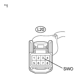
Text in Illustration *1 Front view of wire harness connector
(to A/C Control Assembly)
*2 Front view of wire harness connector
(to Spiral with Sensor Cable Sub-assembly)
Measure the resistance according value(s) in the table below.
Standard Resistance Tester Connection Condition Specified Condition L20-3 (SWO) - L52-10 (AC1) Always Below 1 Ω L20-3 (SWO) - Body ground Always 10 kΩ or higher
NG
REPAIR OR REPLACE HARNESS OR CONNECTOR
OK
REPLACE A/C CONTROL ASSEMBLY Click here
-