FUEL INJECTOR INSTALLATION

-
INSTALL FUEL INJECTOR ASSEMBLY
-
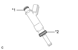
Text in Illustration *1 O-ring *2 Injector Vibration Insulator Install a new injector vibration insulator and O-ring to each fuel injector assembly.
-
Apply a light coat of gasoline or spindle oil to the contact surfaces of the new O-ring on each fuel injector assembly.
-
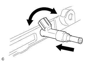
While turning the fuel injector assembly left and right, install it onto the fuel delivery pipe sub-assembly.
Note
-
Do not damage the fuel injector assembly or O-ring.
-
Do not twist the O-ring.
-
After installing each fuel injector assembly, check that it turns smoothly. If not, replace the O-ring with a new one.
-
-
-
INSTALL NO. 1 DELIVERY PIPE SPACER
-
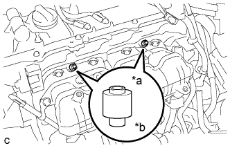
Text in Illustration *a Delivery Pipe Side *b Cylinder Head Side Install the 2 No. 1 delivery pipe spacers onto the cylinder head.
Note
Install the No. 1 delivery pipe spacers in the correct direction.
-
-
INSTALL FUEL DELIVERY PIPE SUB-ASSEMBLY
-
Install the fuel delivery pipe sub-assembly with the 4 fuel injector assemblies and install the 2 bolts.
- Torque:
- 21 N*m { 214 kgf*cm, 15 ft.*lbf }
Note
-
Be careful not to drop the fuel injector assemblies when installing the fuel delivery pipe sub-assembly.
-
Check that the fuel injector assemblies rotate smoothly after installing the fuel delivery pipe sub-assembly.
-
Install the bolt to secure the fuel delivery pipe sub-assembly.
- Torque:
- 21 N*m { 214 kgf*cm, 15 ft.*lbf }
-
-
INSTALL NO. 1 WATER BY-PASS PIPE (w/o EGR System)
-
Install the No. 1 water by-pass pipe with the 2 bolts and nut.
- Torque:
- 21 N*m { 214 kgf*cm, 15 ft.*lbf }
-
Engage the clamp to connect the engine wire.
-
-
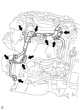
CONNECT FUEL TUBE SUB-ASSEMBLY
-
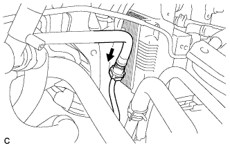
Push the fuel tube connector into the fuel pipe until the fuel tube connector makes a "click" sound.
Note
-
Before connecting the fuel tube connector and fuel pipe, check that there is no damage or foreign matter on the connecting part of the fuel pipe.
-
After connecting the fuel tube connector and fuel pipe, check that they are securely connected by pulling on them.
-
-
Engage the claw to install the No. 1 fuel pipe clamp.
-
-
CONNECT ENGINE WIRE
-
Install the bolt.
- Torque:
- 8.3 N*m { 85 kgf*cm, 73 in.*lbf }
-
Connect the 4 fuel injector connectors.
-
Connect the 4 connectors.
-
Engage the 2 clamps to connect the engine wire.
-
-
INSTALL EGR WITH COOLER PIPE SUB-ASSEMBLY (w/ EGR System)
-
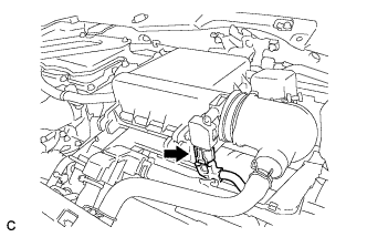
INSTALL AIR CLEANER HOSE ASSEMBLY (w/o EGR System)
-
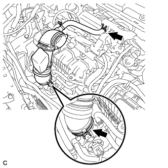
Install the air cleaner hose assembly and tighten the hose clamp.
-
Connect the ventilation hose to the cylinder head cover sub-assembly.
-
-
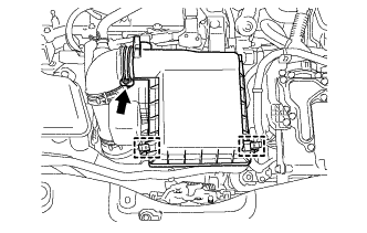
INSTALL AIR CLEANER CASE (w/o EGR System)
-
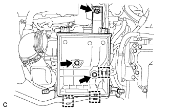
Install the air cleaner case with the 3 bolts.
- Torque:
- 7.0 N*m { 71 kgf*cm, 62 in.*lbf }
-
Connect the No. 4 water by-pass hose to the air cleaner case with the 3 clamps.
-
Install the air cleaner filter element.
-
-
INSTALL INLET AIR CLEANER ASSEMBLY (w/o EGR System)
-
Install the inlet air cleaner assembly with the 2 bolts.
- Torque:
- 7.0 N*m { 71 kgf*cm, 62 in.*lbf }
-
-
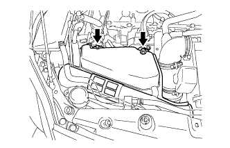
INSTALL AIR CLEANER CAP SUB-ASSEMBLY (w/o EGR System)
-
Install the air cleaner cap sub-assembly with the 2 clamps.
-
Connect the air cleaner hose assembly and tighten the hose clamp.
-
Connect the connector.
-
-
INSTALL REAR NO. 3 FLOOR BOARD
-

Engage the 2 guides to install the rear No. 3 floor board.
-
-
INSTALL REAR DECK FLOOR BOX
-
Install the rear deck floor box.
-
-
INSTALL REAR NO. 2 FLOOR BOARD
-

Engage the 3 guides <A>.
-
Engage the 2 guides <B> and install the rear No. 2 floor board as shown in the illustration.
-
-
CONNECT CABLE TO NEGATIVE AUXILIARY BATTERY TERMINAL
Note
When disconnecting the cable, some systems need to be initialized after the cable is reconnected Click here.
-
INSPECT FOR FUEL LEAK
-
Check fuel pump operation.
-
Connect the intelligent tester to the DLC3.
-
Turn the power switch on (IG).
Note
Do not start the engine.
-
Turn the intelligent tester on.
-
Enter the following menus: Powertrain / Engine and ECT / Active Test / Control the Fuel Pump /Speed.
-
Check for pressure in the fuel inlet tube from the fuel line. Check that sounds of fuel flowing from the fuel tank can be heard. If no sounds can be heard, check the integration relay, fuel pump, ECM and wiring connectors.
-
-
Inspect for fuel leaks.
-
Check that there is no fuel leakage after performing maintenance anywhere on the fuel system. If there is a fuel leak, repair or replace parts as necessary.
-
-
Turn the power switch off.
-
Disconnect the intelligent tester from the DLC3.
-
-
INSTALL NO. 2 CYLINDER HEAD COVER (w/o EGR System)
-
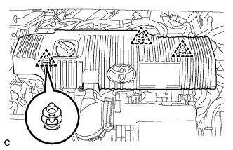
Engage the 3 clips to install the cover.
Note
-
Be sure to engage the clips securely.
-
Do not apply excessive force or hit the cover to engage the clips. This may cause the cover to break.
-
-