CONTINUOUSLY VARIABLE TRANSAXLE SYSTEM, Diagnostic DTC:P0741, P2757
| DTC Code | DTC Name |
|---|---|
| P0741 | Torque Converter Clutch Solenoid Performance (Shift Solenoid Valve SL) |
| P2757 | Torque Converter Clutch Pressure Control Solenoid Control Circuit Performance (Shift Solenoid Valve DSU) |
DESCRIPTION
The ECM uses shift solenoid valves SL and DSU to perform lock-up control in response to the driving conditions.
Note
If any parts inside the torque converter assembly are damaged, DTC P0741/64 and P2757/64 could be output. In this case, make sure to replace both the torque converter assembly and the continuously variable transaxle assembly as broken pieces may have entered through the oil passages and some of them may be present in the continuously variable transaxle assembly.
Tech Tips
Shift solenoid valve DSU controls the lock-up clutch pressure in response to the input torque.
| DTC Code | DTC Detection Condition
|
Trouble Area |
|---|---|---|
| P0741 |
|
|
| P2757 |
|
|
|
MONITOR DESCRIPTION
When performing lock-up control (on/off) of the torque converter, the ECM compares the rotating speeds of the turbine (NT) and engine (NE) to detect mechanical malfunctions in the shift solenoid valves SL and DSU. When the rotating speeds are different than expected, the ECM detects the problem, illuminates the MIL and stores the DTC.
INSPECTION PROCEDURE
PROCEDURE
-
CHECK DTC OUTPUT (IN ADDITION TO DTC P0741 AND P2757)
-
Connect the intelligent tester to the DLC3.
-
Turn the ignition switch to ON.
-
Turn the intelligent tester on.
-
Enter the following menus: Powertrain / Engine and ECT / DTC.
-
Read the DTCs using the tester.
Result Result Proceed to Only P0741 and/or P2757 is output A P0741 and/or P2757 and other DTCs are output B Tech Tips
If any other DTCs besides P0741 or P2757 are output, perform troubleshooting for those DTCs first.
B 
GO TO DTC CHART Click here
A 
-
-
CLEAR DTC
-
Clear the DTC Click here.
NEXT
-
-
PERFORM DRIVE TEST
CAUTION:
Strictly observe posted speed limits, traffic laws and road conditions when performing the road test.
Note
-
This test must be conducted after checking and confirming that the engine is operating normally.
-
Perform this test while the CVT fluid temperature is between 50 and 100°C (122 and 212°F).
-
Perform the test with the A/C off and no electrical load.
-
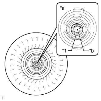
Make sure to replace both the torque converter assembly and the continuously variable transaxle assembly if any parts inside the torque converter assembly are damaged. Broken pieces may have entered through the oil passages and some of them may be present in the continuously variable transaxle assembly.
Text in Illustration *1 Oil seal *a Example of the damage *b Damage Tech Tips
-
Lock-up control will not operate when the CVT fluid temperature is 40°C (104°F) or less and the vehicle speed is 60 km/h (37 mph) or less, or when the CVT fluid temperature is 5°C (41°F) or less.
-
Lock-up control will not operate when the engine coolant temperature is 30°C (86°F) or less.
-
The lock-up off vehicle speed may vary depending on the electrical load, air conditioning and brake operations.
-
Connect the intelligent tester to the DLC3.
-
Start the engine.
-
Turn the intelligent tester on.
-
Enter the following menus: Powertrain / Engine and ECT / Data List / SPD (NT), Lock Up and Engine Speed.
-
Check the Data List while driving.
Result Result Proceed to When the lock-up is on, the turbine speed is lower than the engine speed. A When the lock-up is off, the turbine speed is equal to the engine speed. When the lock-up is on, the turbine speed is equal to the engine speed. B When the lock-up is off, the turbine speed is lower than the engine speed.
B 
A
-
-
REPLACE CONTINUOUSLY VARIABLE TRANSAXLE ASSEMBLY
-
Replace the continuously variable transaxle assembly Click here.
NEXT
-
-
REPLACE TORQUE CONVERTER ASSEMBLY
NEXT
-
PERFORM INITIALIZATION
Note
-
Performing reset memory will clear the learned values of both the yaw rate sensor (deceleration sensor 0 point calibration) and CVT oil pressure (CVT oil pressure calibration). Make sure to perform reset memory, yaw rate sensor 0 point calibration and CVT oil pressure calibration when replacing any of the parts shown in the following table:
Replaced Part
-
Continuously variable transaxle assembly
-
ECM
-
Oil pressure sensor
-
Yaw rate sensor
-
-
After performing reset memory, always perform yaw rate sensor (deceleration sensor 0 point) calibration first, and then CVT oil pressure calibration.
-
Always perform 0 point calibration with the vehicle on level ground.
-
Do not shake or vibrate the vehicle during 0 point calibration.
-
Using the intelligent tester, perform reset memory, deceleration sensor 0 point calibration and CVT oil pressure calibration Click here.
-
Check that no DTC is stored.
NEXT 
END
-